Plastic clip

Inactive Publication Date: 2002-10-01
LAWRENCE LLOYD L
View PDF16 Cites 100 Cited by
  • Summary
  • Abstract
  • Description
  • Claims
  • Application Information

AI Technical Summary

Problems solved by technology

The advantages of sheet-metal or metal ribbon for the manufacture of clips have been difficult to overcome.
For example, plastics are typically non-abrasive and non-conductive, and are thus innocuous to delicate surfaces or surfaces that must be insulated from electrical currents or protected from galvanic or stress corrosion.
Unfortunately, however, it is difficult to t

Method used


Image

  • Plastic clip
  • Plastic clip
  • Plastic clip

Examples


Embodiment Construction

While the invention will be described and disclosed here in connection with certain preferred embodiments, the description is not intended to limit the invention to the specific embodiments shown and described here, but rather the invention is intended to cover all alternative embodiments and modifications that fall within the spirit and scope of the invention as defined by the claims included herein as well as any equivalents of the disclosed and claimed invention.

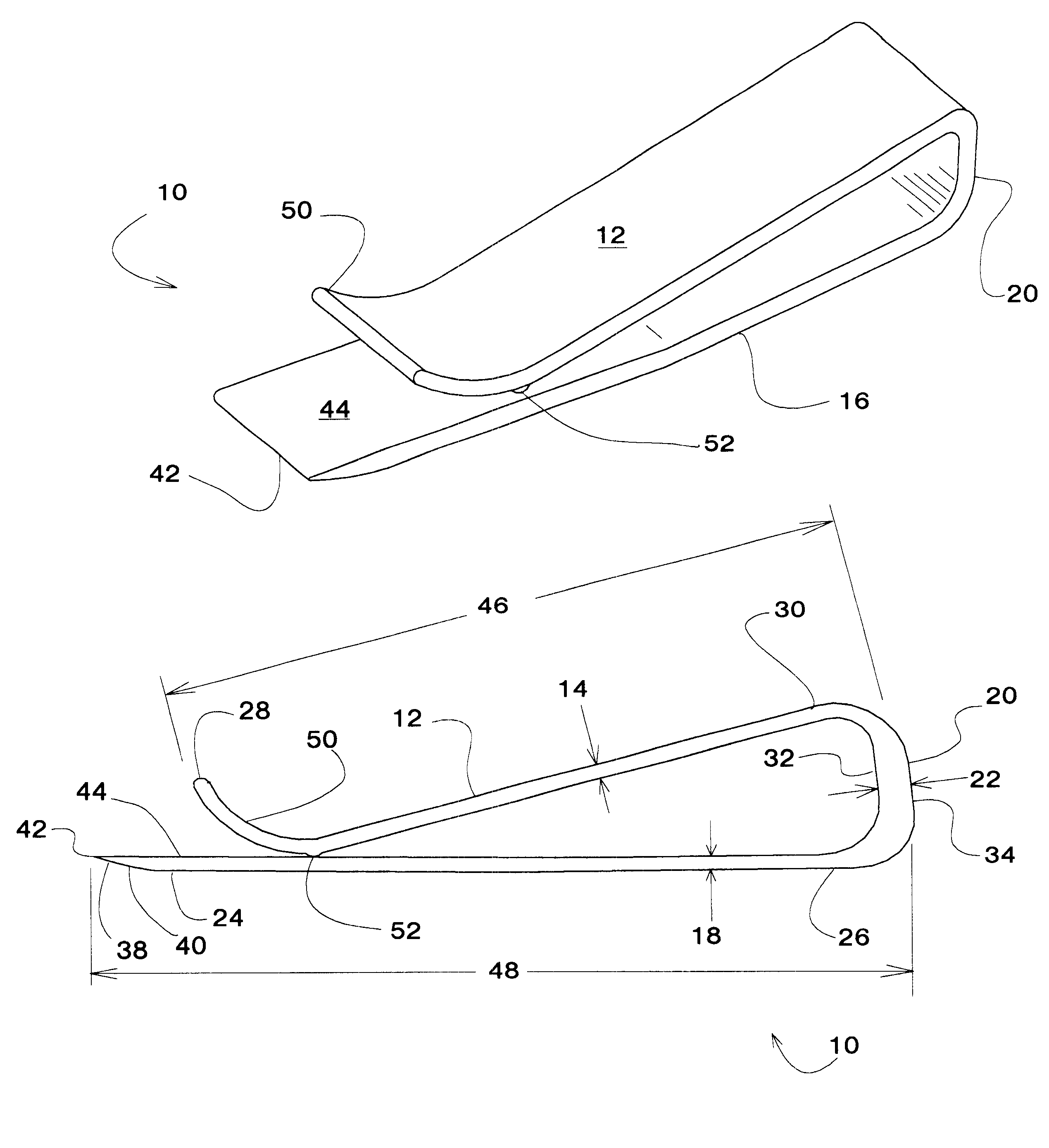
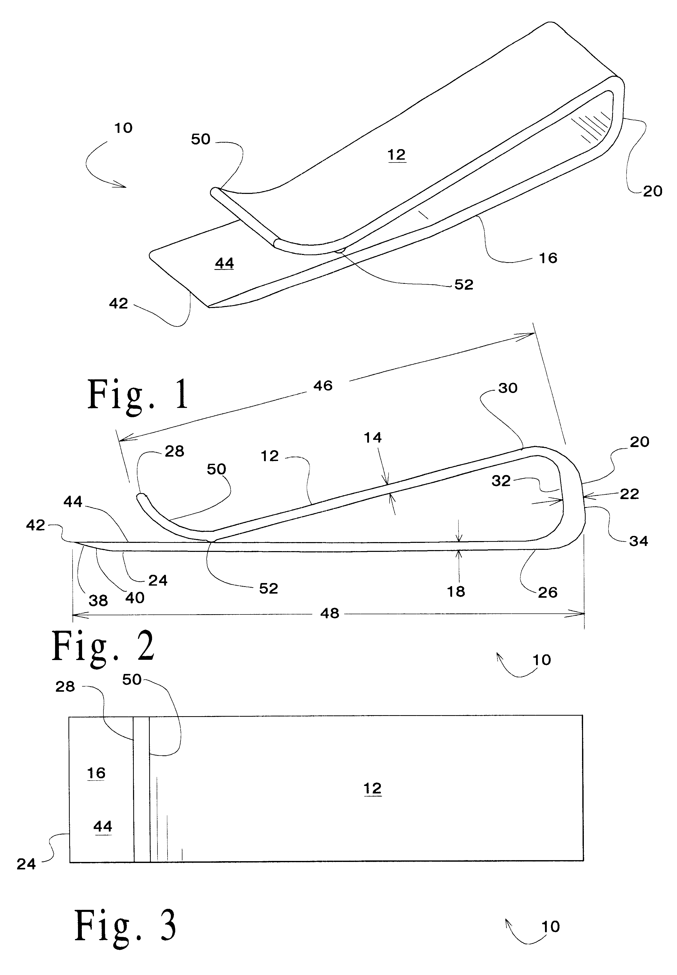
Turning now to FIG. 1 where a plastic clip 10 incorporating principles taught herein has been illustrated. As illustrated, a highly preferred embodiment of the plastic clip 10 includes a first leg 12 of a first thickness 14, and a second leg 16 of a second thickness 18. The first leg 12 and the second leg 16 are joined by a bridging section 20, which holds and biases the first leg 12 against the second leg 16. As will be described in greater detail below, a highly preferred embodiment of the plastic clip 10 will be of uni...


PUM

PropertyMeasurementUnit
Thicknessaaaaaaaaaa
Lengthaaaaaaaaaa
Plasticityaaaaaaaaaa

Abstract

A plastic clip of unitary, one piece construction, and a method for making the same is disclosed. The clip includes a first leg of a first thickness, a second leg of a second thickness, and a bridging section joining the first leg and the second leg, the bridging section being of a dimension that upon cooling or curing of the plastic material, the bridging section biases the first leg against the second leg.

Description

(a) Field of the InventionThis invention generally relates to a resilient plastic clip and method for making the clip. More particularly, but not by way of limitation, to a plastic clip having legs or arms that are preloaded or biased directly against one another when the clip is not in use.(b) Discussion of Known ArtThe advantaged of a clip made from spring materials have long been recognized for their simplicity and ease of use. Most known clips consist of a pair of legs or arms that are biased against one another by a spring. Many metal clips take advantage of the modulus of elasticity of sections of metal ribbon to produce an integral clip, having both legs and the spring biasing the legs towards one another made from a single, continuous, section of metal ribbon. Examples of this kind of device can be found in U.S. Pat. No. 609,486 to Wilson shows the use of metal ribbon to create a metal spring. The Wilson device also illustrates the use of legs of uneven length, the shorter l...

Claims


Application Information

Patent Timeline
IPC IPC(8): B42F1/10B42F1/00
CPCB42F1/10Y10T24/1394Y10T24/44769Y10T24/44923Y10T24/205
Inventor LAWRENCE, LLOYD L.
Owner LAWRENCE LLOYD L
Why Eureka
Try Eureka