Sensor element

a technology of sensors and elements, applied in the field of sensors, can solve problems such as the possibility of limited reduction of their siz

Inactive Publication Date: 2002-10-08
ROBERT BOSCH GMBH
View PDF7 Cites 31 Cited by
  • Summary
  • Abstract
  • Description
  • Claims
  • Application Information

AI Technical Summary

Problems solved by technology

A disadvantage of the previously proposed sensor elements is that they have a relativ...

Method used


Image

  • Sensor element
  • Sensor element
  • Sensor element

Examples


Embodiment Construction

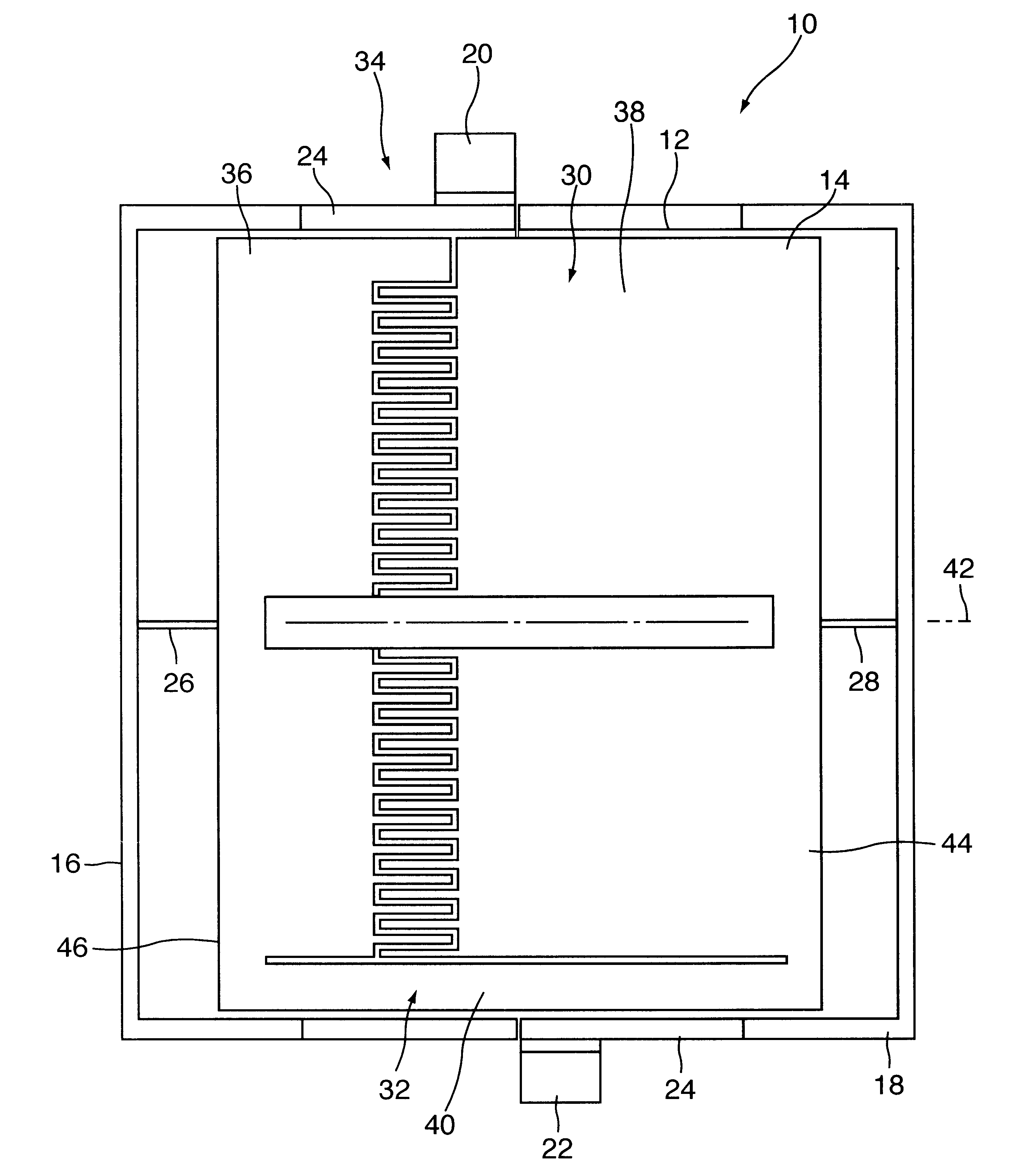
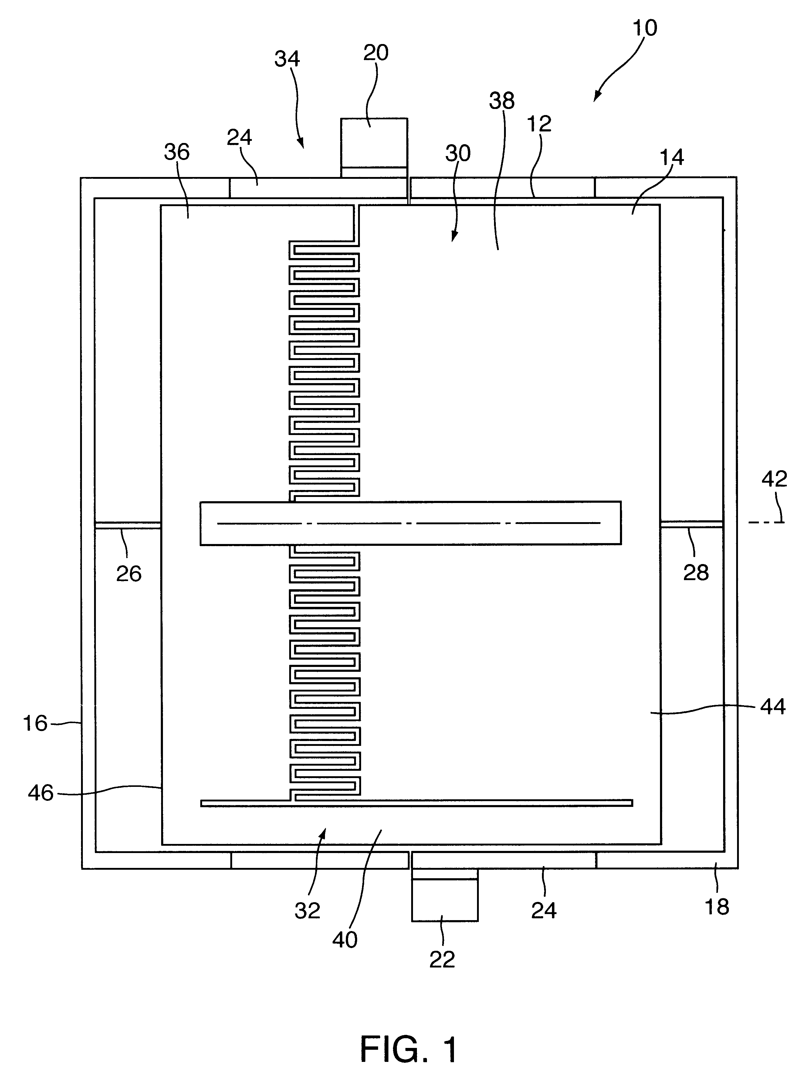
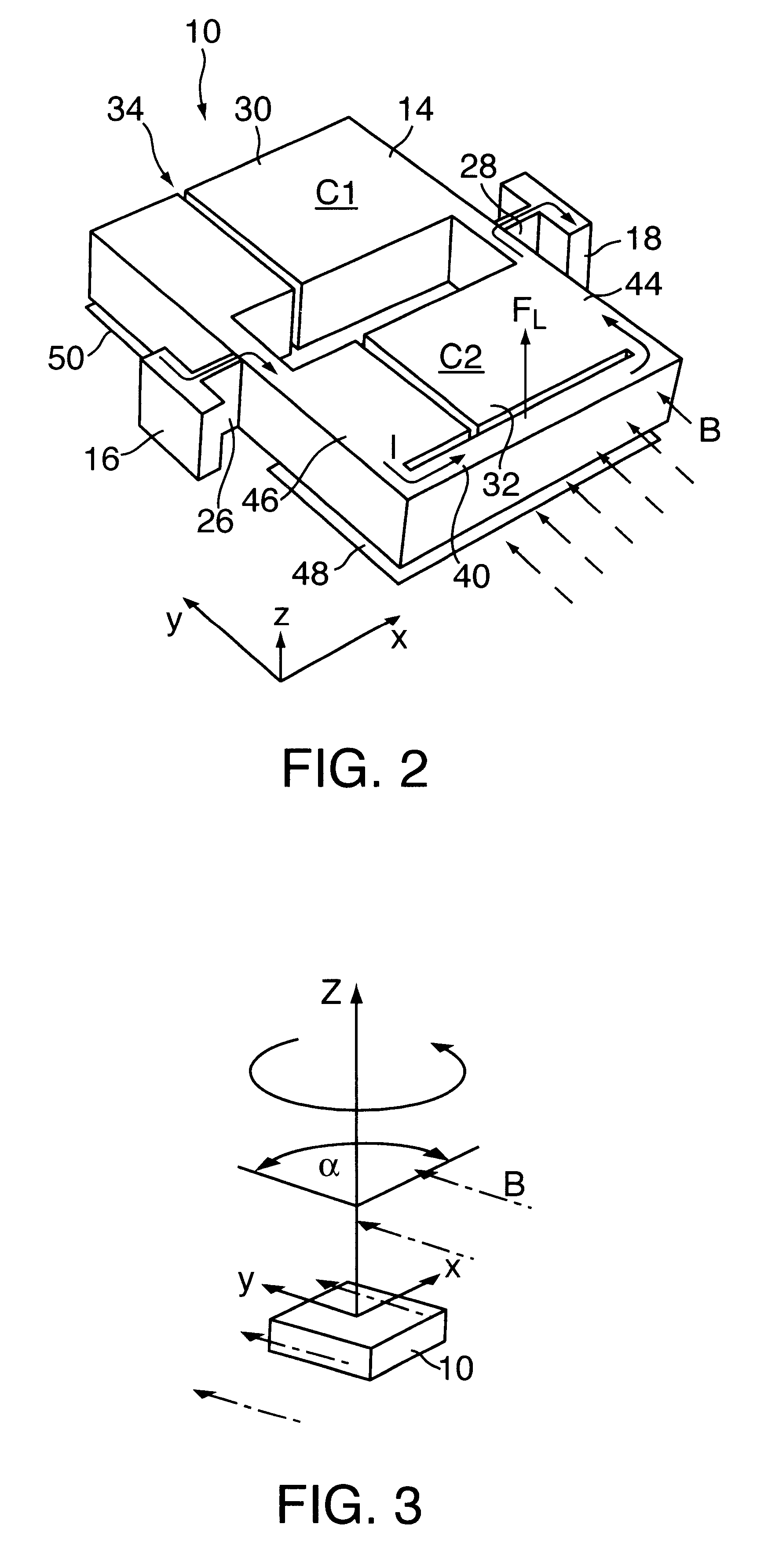
FIG. 1 shows a top view of a sensor element 10. Sensor element 10 is structured on the surface of a wafer (not shown) by the methods of surface micromechanics. The wafer may at the same time have electric circuits for analysis of signals supplied with sensor element 10. These analyzer circuits will not be described in greater detail in the context of the present description.

Silicon may be used as the material for sensor element 10, with electric conductivity of sensor element 10 being achieved by suitable doping.

Sensor element 10 has a frame 12 surrounding a detection medium 14 as seen from above. The frame is designed in two parts, resulting in a left frame half 16 and a right frame half 18, as seen in the top view illustrated in FIG. 1. Frame half 16 is connected to a terminal contact 20 and frame half 18 is connected to a terminal contact 22. Frame halves 16 and 18 have sections 24 having a greater width and thus a larger cross section than the other parts of frame halves 16 and ...


PUM


Abstract

A sensor element, in particular for determining an angle of rotation, has a detection medium whose position varies as a function of a change in a parameter to be measured, where the change in the position of the detection medium leads to a change in an analyzable signal of the sensor element which is influenced by the detection medium. The detection medium has at least one conductor loop carrying current which is exposed to an external magnetic field; the detection medium is rotationally movably mounted so that a rotational motion of the sensor element about an angle of rotation in the plane of the magnetic field is converted into a deflection of the detection medium perpendicular to the magnetic field.

Description

The present invention relates to a sensor element, in particular for determining an angle of rotation, having a detection medium whose position varies as a function of a change in a parameter to be measured, where the change in the position of the detection medium leads to a change in an analyzable signal of the sensor element which is influenced by the detection medium.BACKGROUND INFORMATIONA previously proposed sensor element, for example, operates according to a potentiometric or optical principle are known in precision mechanics. Due to a rotational motion of a part having this sensor element, a change in resistance is triggered, leading to a change in an analyzable electric signal, or in the case of sensor elements that function optically, an optical signal is influenced as a function of a rotational position, so that it generates an analyzable signal, e.g., by way of a photoelectric cell. In addition, Hall sensors are also known, which utilize the effect that, in the case of a...

Claims


Application Information

Patent Timeline
IPC IPC(8): G01D21/02G01R33/028G01B7/00G01B7/30
CPCG01D21/02G01R33/028
Inventor SCHOEFTHALER, MARTINSCHELLIN, RALFMAIHOEFER, BERNDLAERMER, FRANZLUTZ, MARKUSEMMERICH, HARALDKAIENBURG, JOERG
Owner ROBERT BOSCH GMBH
Why Eureka
Try Eureka