Model car display shelf unit

a model car and shelf technology, applied in the direction of display racks, display cabinets, wall tables, etc., can solve the problems of not being able to form a complete cylindrical race track in any size room, not allowing for display, and requiring a lot of work to mount the shelving to the wall

Inactive Publication Date: 2002-10-22
GUILLOT MARK ANTHONY
View PDF13 Cites 26 Cited by
  • Summary
  • Abstract
  • Description
  • Claims
  • Application Information

AI Technical Summary

Benefits of technology

As best illustrated in FIG. 4, the display shelf unit 1 generally comprises a top shelf face surface 115 sloped at an obtuse angle represented by the letter B, from mounting channel front surface 5, shelf mounting receptacle 2, front electrical power receptacle surface 9, bottom outer surface 11 at an acute angle represented by the letter A from bottom end of top shelf face surface 115, rear vertical surface 15 of shelf bottom, a pair of edges, left end 44a, (right end 44b not seen in FIG. 4), graphic board 20 illustrated in FIGS. 7a and 7b and mounting bracket 58 Illustrated in FIGS. 5a, 5b, 5c, 5d and 5e. The top shelf face surface 115 has six equally spaced individual sloped surfaces 6 and one shorter sloped surface 7 and when combined they form six equally spaced grooves 8. The material used in forming the shelf can be any lightweight durable plastic or polymer of color to represent any surface of any type racetrack or roadway. As illustrated in FIGS. 27, 33, 42 and 43 the display shelf unit 1 can be cut with a saw to fit any space by sliding it into a cutting guide tool 119, 135, 143 or 144. It is used to guide the saw to make a perpendicular cut or mark as desired along all joining surfaces. A modified display shelf unit 1 that has been cut to fit will be indicated on drawings by the numeral 80 as illustrated in FIGS. 1 and 14. In manufacturing the entire display shelf unit 1 it can be sized proportionally to any model cars sold on the market.

Problems solved by technology

The method used to display the model cars only impersonates the track portion of a racetrack and does not replicate an entire life-like racing or any other automobile related display.
The prior art does not allow for a display that would enhance all types of racing backgrounds to create a more realistic life-like display for various and specific types of race tracks and model cars.
To mount the shelving to a wall requires a lot of work and makes it impossible to form a complete cylindrical race track in any size room.
Furthermore the lighting method used is inadequate, bulky, not adjustable and not easily maintained.
Once device is hung on wall, the unattractive mounting hardware, end electrical prongs and wiring is visible from bottom of shelf and allows no storage space for model car containers they were purchased in.
With the prior art, model cars can only be staggered horizontally making model cars appear to be in single file on any one lane and does not allow for various positions for placement of model cars.
The prior art does not have any provisions for custom cutting a shelf to fit any space.
Furthermore once their shelves are in place they cannot be removed from wall without disturbing adjacent shelves that have prongs located on the ends for electrically connecting adjacent tracks together.
When trying to make a partial display, the shelving dangerously exposes electrically conductive prongs embedded at ends of shelving.

Method used


Image

  • Model car display shelf unit
  • Model car display shelf unit
  • Model car display shelf unit

Examples


Embodiment Construction

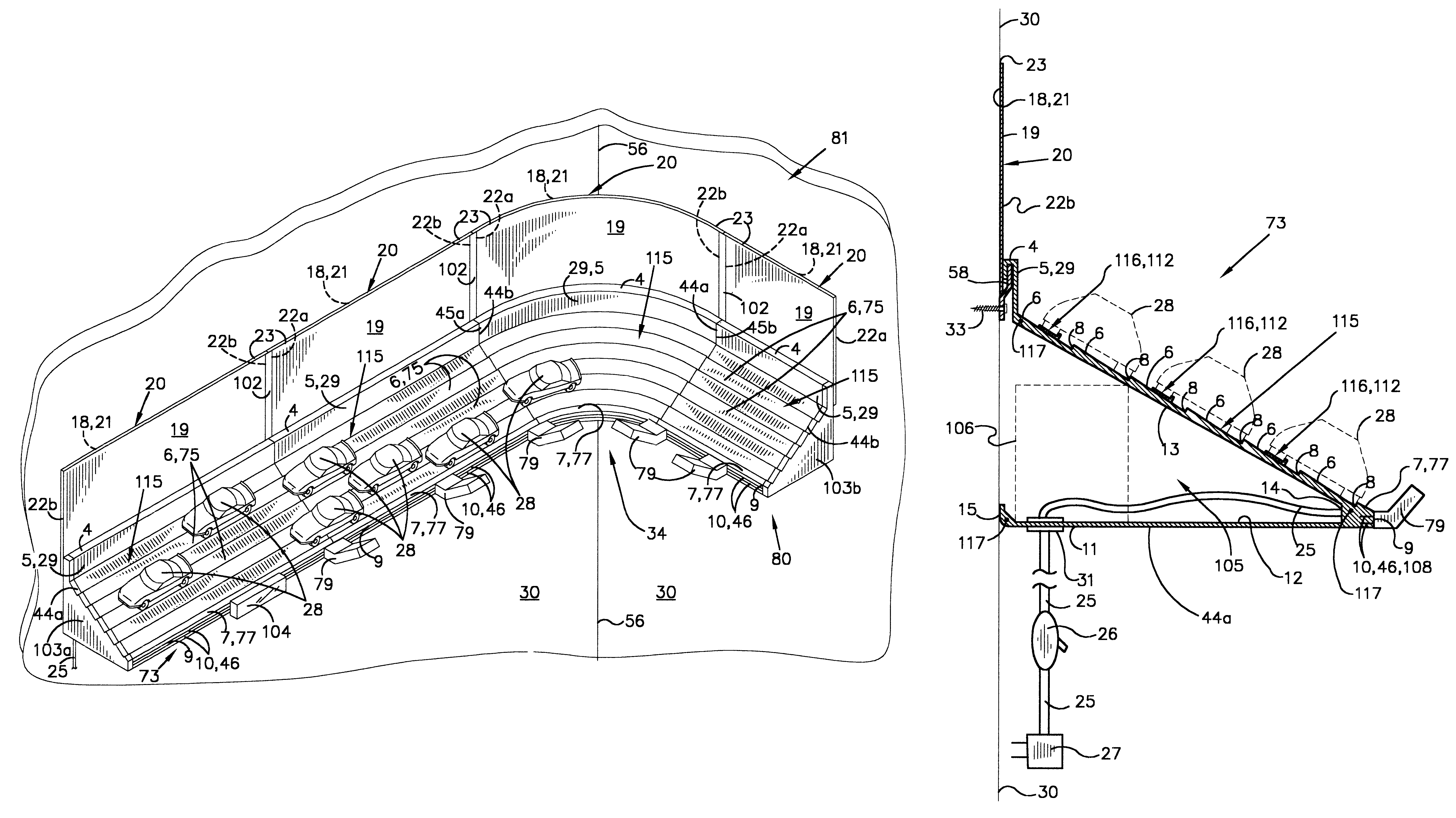
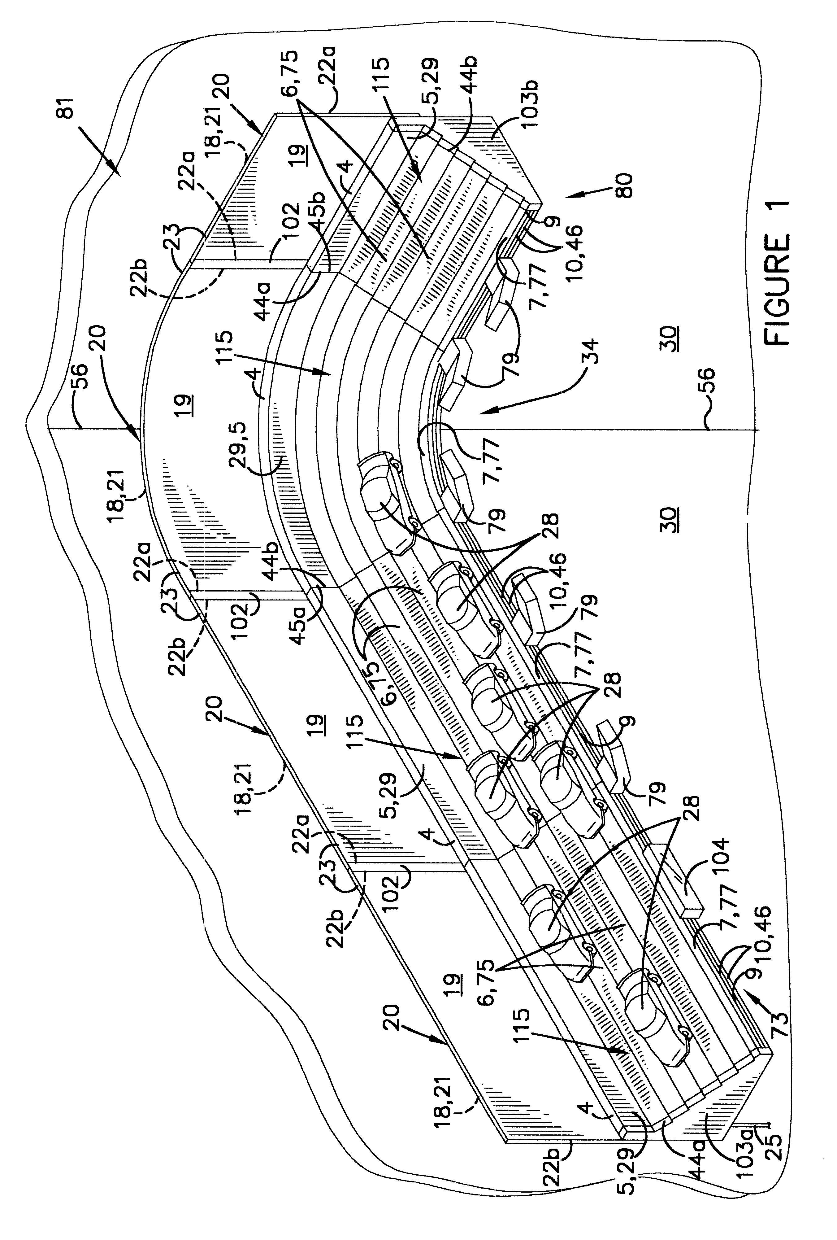
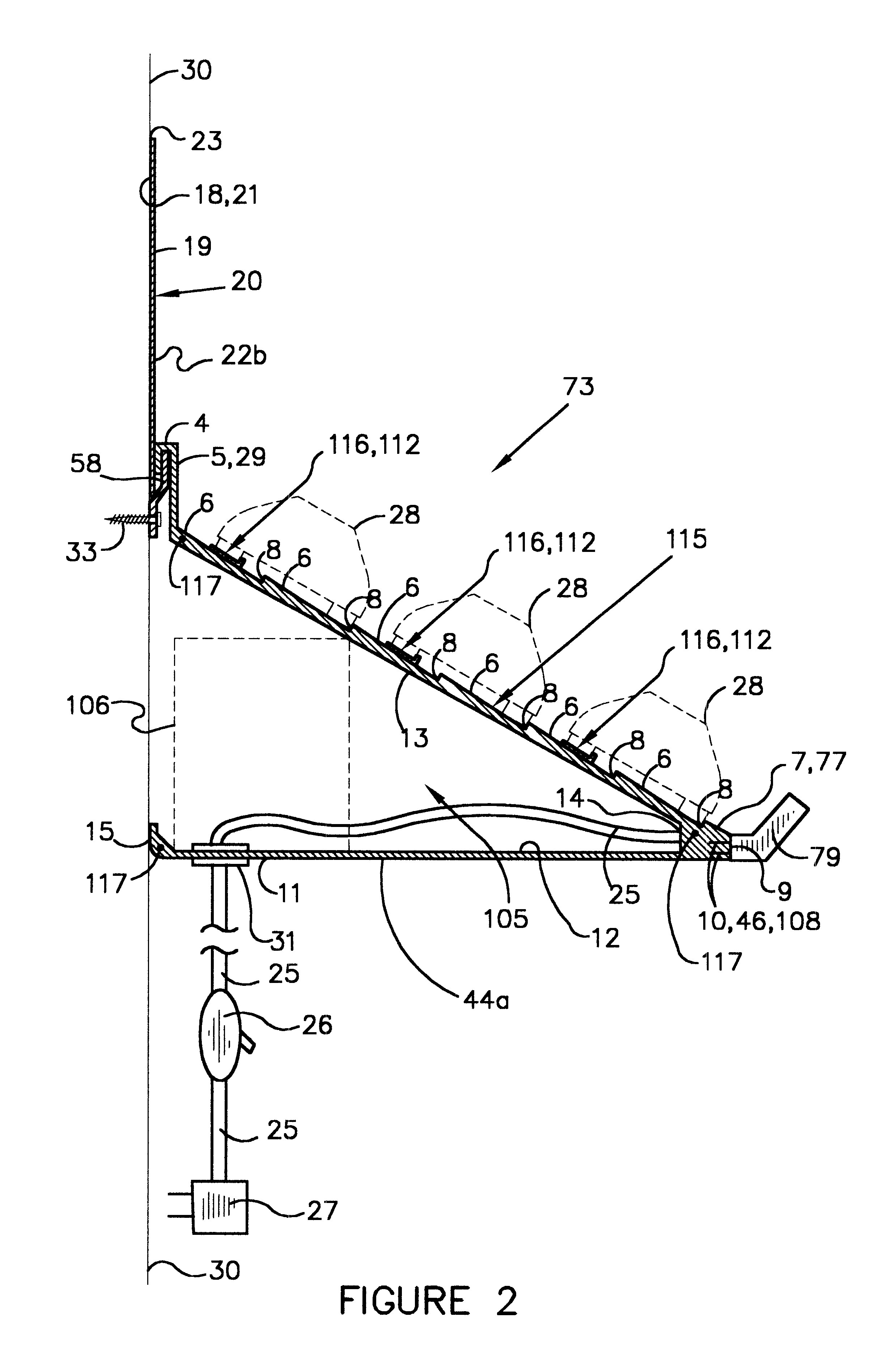
With reference now to the drawings, and in particular to FIGS. 1 through 47 thereof, a new display shelf unit embodying the principles and concepts of the present invention and generally designated by the reference numeral 1 will be described.

Brief Description of Straightaway Shelf Unit

As best illustrated in FIG. 4, the display shelf unit 1 generally comprises a top shelf face surface 115 sloped at an obtuse angle represented by the letter B, from mounting channel front surface 5, shelf mounting receptacle 2, front electrical power receptacle surface 9, bottom outer surface 11 at an acute angle represented by the letter A from bottom end of top shelf face surface 115, rear vertical surface 15 of shelf bottom, a pair of edges, left end 44a, (right end 44b not seen in FIG. 4), graphic board 20 illustrated in FIGS. 7a and 7b and mounting bracket 58 Illustrated in FIGS. 5a, 5b, 5c, 5d and 5e. The top shelf face surface 115 has six equally spaced individual sloped surfaces 6 and one shor...


PUM


Abstract

A new simple easily mounted, attractive life-like shelf for display of model cars and that can allow for storage of their containers thereon. The invention is comprised of a mounting bracket, straight display shelf, curved display shelf, electrical power receptacle, graphic display board and decals. The device includes at least one straightaway display shelf made from at least one piece of material that hangs on mounting bracket attached to a wall. A sloped horizontal top shelf face surface forms the top surface of a race track, graphic decals and that is the length between end edges of the shelf. A electrical power receptacle located near join of said top shelf face surface and shelf bottom for plugging in display lights, signs and any other miscellaneous electrical device. Lighting can be plugged in as required in electrical power receptacle to provide lighting to only those areas desired by facing upward towards the visual side of the model cars on display. A horizontal flat bottom surface at a right angle from a wall and joined to bottom of top shelf face surface forming an acute angle at join. The length extends between the edges of the shelf that when engaged to a wall form a storage space for model car containers. Model cars can be attached to top shelf face surface with various types wheel chucks to allow for any combination of arranging model cars onto track.

Description

1. Field of InventionThe present invention relates to devices for displaying model cars and associated figurines. It is important for the collector of model cars to keep their original containers that they were purchased in so that the value of the collection is maintained. The present invention allows for storage of said containers so that they do not take up other valuable space and furthermore provide protection of the containers. More specifically, the invention relates to a wall or free standing shelf unit for displaying model cars in various positions. The present invention can also be used by the retailers of model cars for displaying model cars for the sale to consumers.2. Description of the Prior ArtThe uses of displaying models and figurines is known in the prior art. The method used to display the model cars only impersonates the track portion of a racetrack and does not replicate an entire life-like racing or any other automobile related display. The prior art does not a...

Claims


Application Information

Patent Timeline
Patent Type & Authority Patents(United States)
IPC IPC(8): A47F11/00A47F11/10A47F7/00A47F5/16
CPCA47F5/16A47F7/00A47F11/10A47F2007/0092
Inventor GUILLOT, MARK ANTHONY
Owner GUILLOT MARK ANTHONY
Why Eureka
Try Eureka