Image display device and driving method thereof

a technology of image display device and driving method, which is applied in the direction of 3d-image rendering, instruments, computing, etc., can solve the problems of ghosting 3d crosstalk, difficult to effectively improve the 3d crosstalk using the existing odc logic and compensation values, and motion blurring

Active Publication Date: 2011-11-10
LG DISPLAY CO LTD
View PDF3 Cites 39 Cited by
  • Summary
  • Abstract
  • Description
  • Claims
  • Application Information

AI Technical Summary

Problems solved by technology

The response delay of liquid crystal causes motion blurring when a left-eye image is changed to a right-eye image or when a right-eye image is changed to a left-eye image while the LCD generates a 3D image to result in 3D crosstalk in the form of a ghost.
However, the black data frame B is located before the left-eye data frame L or right-eye data frame R in FIG. 2, and thus it is difficult to effectively improve the 3D crosstalk using the existing ODC logic and compensation values.

Method used


Image

  • Image display device and driving method thereof
  • Image display device and driving method thereof
  • Image display device and driving method thereof

Examples


Embodiment Construction

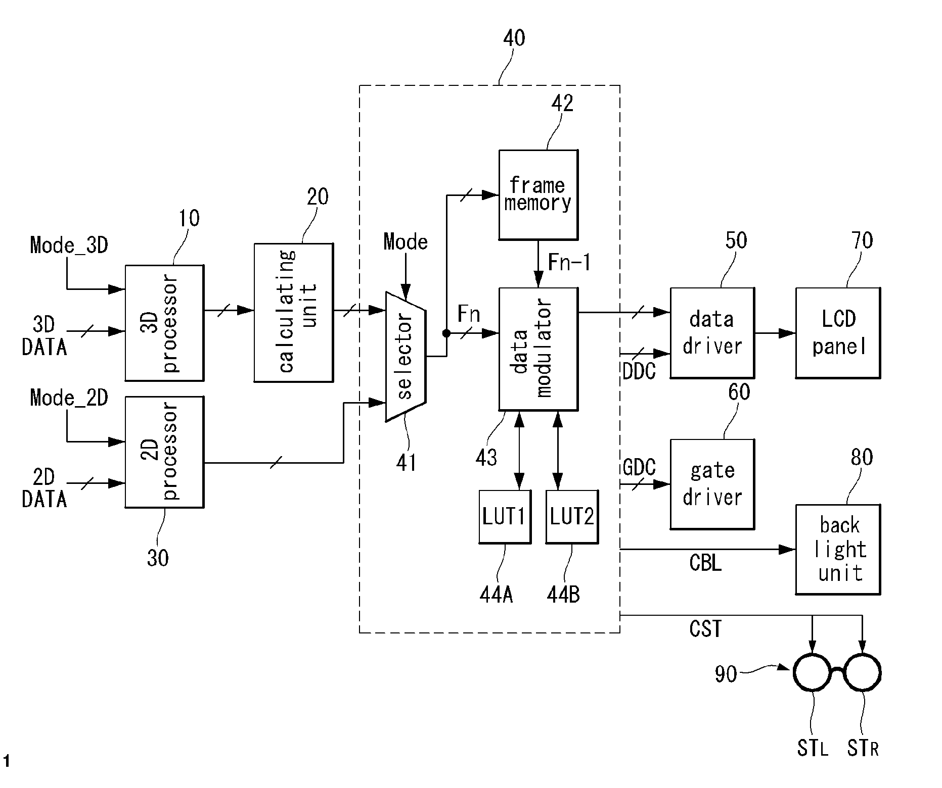
[0037]Hereinafter, an implementation of this document will be described in detail with reference to FIGS. 3 through 11.

[0038]FIG. 3 is a flowchart showing an implementation of a method of driving an image display device and FIG. 4 illustrates insertion of a rest frame between data frames. FIGS. 5 and 7 illustrate exemplary operations of reflecting gray-scale information of a previous data frame in a reset frame, and FIGS. 6 and 8 illustrate exemplary first look-up tables respectively corresponding to FIGS. 5 and 7.

[0039]Referring to FIG. 3, it is determined whether a current driving mode is a 3D mode with reference to an input mode signal in operations S10 and S20.

[0040]When it is determined that the current driving mode corresponds to the 3D mode in operation S20, 3D input frames composed of 3D data inputted from an external video source are separated into left-eye data frames L for displaying left-eye images and right-eye data frames R for displaying right-eye images in operation ...


PUM


Abstract

A method of driving an image display device comprises inserting a reset frame displaying black data between neighboring data frames alternately displaying left-eye data and right-eye data; reflecting gray-scale information of an (n−2)th data frame in a reset frame corresponding to an (n−1)th frame through a predetermined data calculating operation; detecting a data variation between the (n−1)th reset frame and an nth data frame, reading a compensation value corresponding to the detection result from a lookup table, and modulating input data of the nth data frame using the read compensation value; and inverting the polarity of the modulated data according to N frame inversion (N is a multiple of 4) and applying the data having the inverted polarity to a display panel.

Description

[0001]This application claims the benefit of Korean Patent Application No. 10-2010-0042969 filed on May 7, 2010, which is incorporated herein by reference for all purposes as if fully set forth herein.BACKGROUND[0002]1. Field[0003]This document relates to an image display device and a driving method thereof for improving picture quality.[0004]2. Related Art[0005]With the advancement of various image processing techniques, image display systems capable of selectively displaying 2D images 3D images are developed.[0006]Methods of generating 3D images are divided into a stereoscopic technique and an autostereoscopic technique.[0007]The stereoscopic technique uses disparity images of left and right eyes, which have high 3D effect, and includes a stereoscopic method and an autostereoscopic method which are practically used. The autostereoscopic method provides an optical plate such as a parallax barrier for separating optical axes of left and right disparity images from each other before ...

Claims


Application Information

Patent Timeline
Patent Type & Authority Applications(United States)
IPC IPC(8): G06T15/00G09G5/10
CPCH04N13/0438G09G3/003G09G2340/16G09G2310/061G09G2320/0285G09G3/3648H04N13/341
Inventor SON, HYEONHOKIM, EUITAEPARK, JOONYOUNGLEE, JEONGKI
Owner LG DISPLAY CO LTD
Why Eureka
Try Eureka