Panel Display Module and Manufacturing Method Thereof

a technology of panel display module and manufacturing method, which is applied in the manufacture of electric discharge tube/lamp, instruments, lighting and heating apparatus, etc., to achieve the effect of increasing the stability of the positional relationship and avoiding separation

Active Publication Date: 2011-09-29
AU OPTRONICS CORP
View PDF2 Cites 40 Cited by
  • Summary
  • Abstract
  • Description
  • Claims
  • Application Information

AI Technical Summary

Benefits of technology

It is another object of the present invention to provide a panel display module and a manufacture method thereof that allows the panel display module to avoid the display panel included therein from damage.
It is yet another object of the present invention to provide a panel display module and a manufacture method thereof that allows the display panel to avoid separation from or movement relative to the backlight module.
The panel display module includes a backlight module, a display panel, a clear cover, and reinforced glue. The backlight module has a frame and a light source module. The light source module is disposed within the frame and encircled by the frame. The frame can define the position of the light source module and the position of any other internal components and provides structural protection. The display panel is disposed within the frame on the light exiting side of the light source. The clear cover is disposed and glued on the side of the display panel opposite to the light source module.
The reinforced glue is distributed encircling the frame and adheres the frame and the clear cover on the portions protruding from the display panel. The reinforced glue has a first side and a second side adhering to the frame and the clear cover, respectively. When the panel display module experiences an external force, the reinforced glue can increase the stability of the positional relationship between the clear cover and the frame while preventing the display panel from separation from or movement relative to the frame induced by the pulling of the clear cover.

Problems solved by technology

However, because unavoidable mishaps from external forces on the electronic devices by the users are bound to occur, the structural integrity of display panels has become an important product design consideration.

Method used


Image

  • Panel Display Module and Manufacturing Method Thereof
  • Panel Display Module and Manufacturing Method Thereof
  • Panel Display Module and Manufacturing Method Thereof

Examples


Embodiment Construction

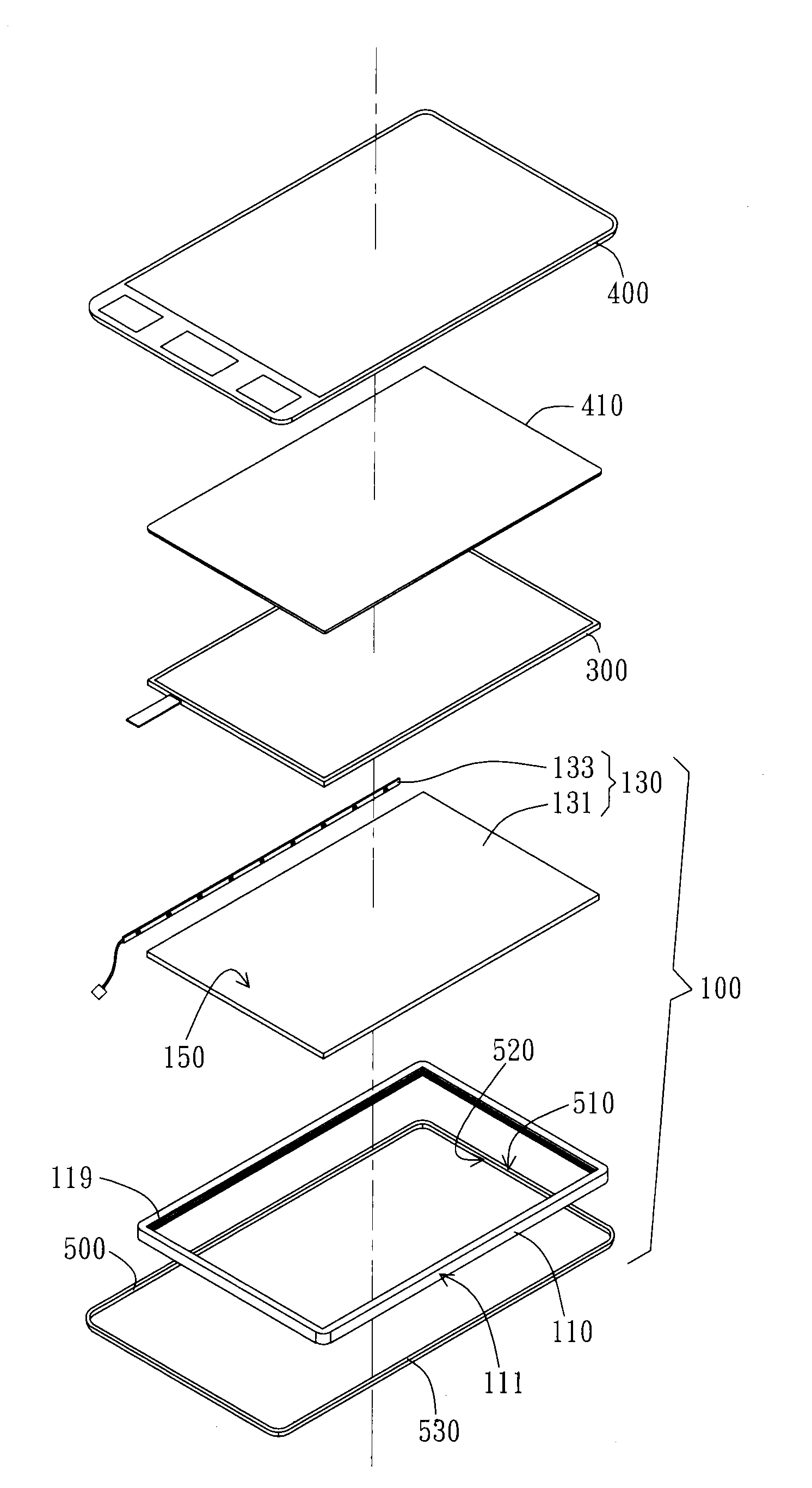
The present invention provides a panel display module and a manufacturing method thereof. In addition, the present invention also includes electronic devices incorporating the above mentioned panel display module. In a preferred embodiment, electronic devices using the panel display module include mobile phones, personal digital assistants (PDAs), laptop computers, personal computers, digital compact dictionaries, handheld entertainment devices, digital cameras, et cetera.

As shown in FIG. 2, the panel display module includes a backlight module 100, a display panel 300, a clear cover 400, and reinforced glue 500. Backlight module 100 has a frame 110 and a light source module 130. Frame 110 is preferably made of plastic or polymer materials. However, in other embodiments, frame 110 can be made of metal or other materials. In the present embodiment, light source module 130 is implemented with edge type light source module and includes a light guide plate 131 and a light source 133. Lig...


PUM


Abstract

A panel display module and a manufacture method thereof are disclosed. The panel display includes a backlight module, a display panel, a clear cover, and reinforced glue. The backlight module has a light source module and a frame that positions the light source module and other elements to provide structural protection. The display panel is disposed on the light exiting side of the light source module. The clear cover is disposed on one side of the display panel opposite to the light source module. The reinforced glue is distributed encircling the frame and adheres respectively to the frame and to the portion of the clear cover protruding over the display panel. The reinforced glue has a first side adhering onto the frame and a second side adhering onto the clear cover.

Description

BACKGROUND OF THE INVENTION1. Field of the InventionThe present invention generally relates to a panel display module.Particularly, the present invention relates to a reinforced structure for panel display module and a manufacture method thereof.2. Description of the Prior ArtLiquid crystal display (LCD) panels and numerous alternative display panels have been used in various electronic devices. In the past few years in particular, handheld electronic devices have been reinvigorated with liquid crystal display panels. Mobile phones, personal digital assistants, laptop computers, hand-held entertainment devices, and digital cameras are examples of devices that have practical use of liquid crystal displays to further enhance image effects. However, because unavoidable mishaps from external forces on the electronic devices by the users are bound to occur, the structural integrity of display panels has become an important product design consideration.FIG. 1A and FIG. 1B illustrate a con...

Claims


Application Information

Patent Timeline
Patent Type & Authority Applications(United States)
IPC IPC(8): F21V7/22G06F3/041H05K7/00H01J9/24
CPCG02F1/133308G02F1/133608G06F2203/04103G06F3/041G06F3/044G02F2202/28G06F1/1643
Inventor LO, SUPAI, CHING-CHIEHLIU, YUNG-CHIHHUANG, REN-WEI
Owner AU OPTRONICS CORP
Why Eureka
Try Eureka