Display board system

a display board and display board technology, applied in the direction of display means, instruments, stands/trestles, etc., can solve the problems of putting the information on display at risk of loss before it can be stored, and the known application is generally not well suited for use in a dynamic work environmen

Inactive Publication Date: 2008-02-05
STEELCASE INC
View PDF219 Cites 44 Cited by
  • Summary
  • Abstract
  • Description
  • Claims
  • Application Information

AI Technical Summary

Problems solved by technology

For example, the mounting interfaces and associated mounting structures holding or providing for the surfaces, are generally either too rigid and inflexible, i.e. immobile and difficult to reconfigure or otherwise to use and store information, as in the case of information that is applied on a fixed wall, or too insubstantial, i.e. highly mobile but otherwise tending to put the information on display at risk of loss before it can be stored, as in the case of information that is posted on a vertical surface (e.g. a bulletin board).
As a result, such known applications are generally not well suited for use in a dynamic work environment, where information is ideally created, displayed (e.g. shared and communicated) and stored in a highly efficient manner.
However, such known display boards have typically not been provided with mounting interfaces that facilitate the use and storage of the display boards in a manner that facilitates “information persistence”—with information on the display boards being made readily available when needed while conveniently stowed when not needed, for example, for a group project.
Moreover, the surface treatments applied to such known display boards are generally limited; such known display boards have typically not been provided with a combination of useful surface treatments that allow information to be conveyed in a variety of media.
Nor have such known display boards been provided with mounting interfaces and associated mounting structures in a system that facilitates the use and interchangeability of the display boards and the use, display and storage of information contained on the display boards.

Method used


Image

  • Display board system
  • Display board system
  • Display board system

Examples


Embodiment Construction

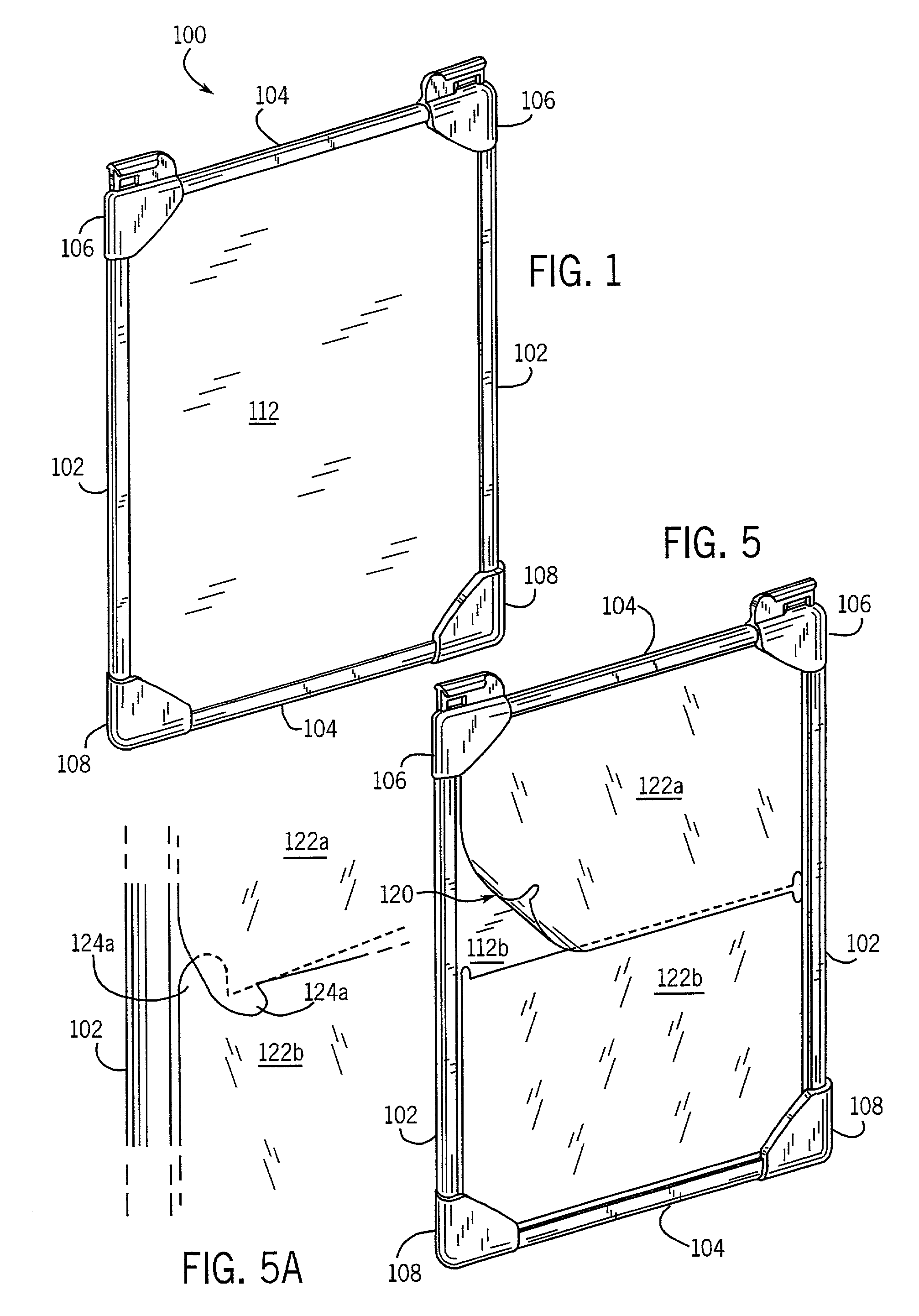
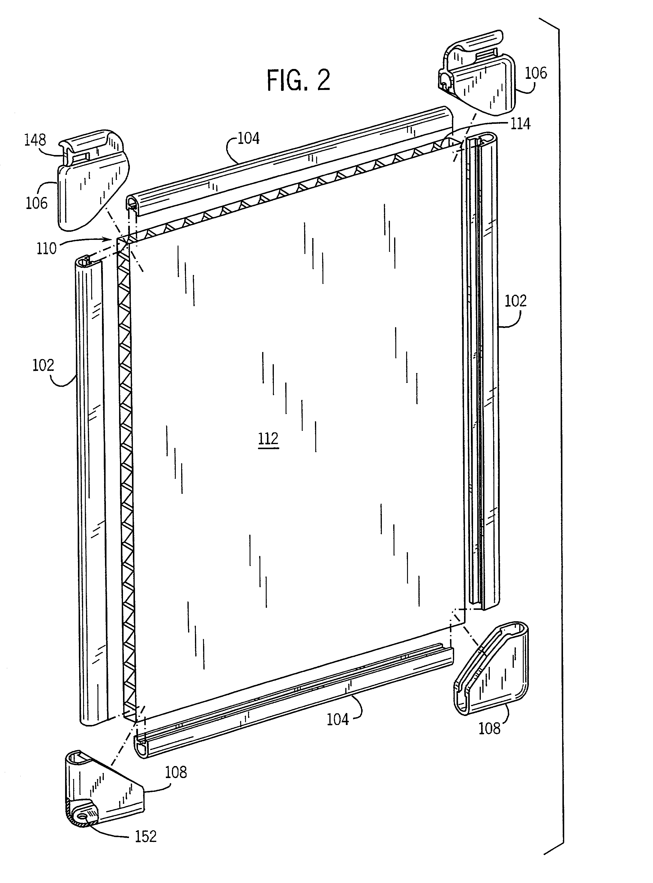
[0123]Referring to FIGS. 1 and 2, a display board 100 is shown according to an exemplary embodiment of the present invention. Display board 100 includes side frame members shown as extruded edge trim members 102 and top and bottom frame members also shown as extruded edge trim members 104. Display board 100 includes four corner members 106 (top) and 108 (bottom) secured to side frame members 102 and top and bottom frame members 104. Display board 100 includes a rigid core 110 providing outer surfaces, namely a front surface 112 and a back surface (not visible).

[0124]According to any preferred embodiment, the display board is configured in a generally symmetrical basic form so that the designation of a “front surface” and “back surface” is essentially arbitrary and dependent upon the orientation of the display board with respect to a person intending to use the display board. As shown in the FIGURES, and as will be apparent to those who review this disclosure, the outer surfaces of t...


PUM


Abstract

An apparatus configured to allow the retention of at least one display board with a mounting structure is disclosed. The apparatus comprises a retaining system. A portion of the retaining system is deformable to retain at least one display board in a press-in, interference engagement. The apparatus may also include a mounting structure such as an easel. An apparatus for use with one or more display boards is also disclosed. The apparatus comprises a mounting structure including a base and a first panel coupled to the base. The first panel is configured to support the one or more display boards and to be selectively movable between a first position and a second position.

Description

CROSS-REFERENCE TO RELATED APPLICATIONS[0001]The present invention claims priority from U.S. patent application Ser. No. 09 / 563,098 titled “DISPLAY BOARD SYSTEM” filed May 2, 2000, now U.S. Pat. No. 6,647,652, the full and entire disclosure of which is hereby incorporated herein by reference, which is a continuation-in-part of U.S. patent application Ser. No. 09 / 182,999, filed Oct. 30, 1998, now U.S. Pat. No. 6,272,779, the full and entire disclosure of which is hereby incorporated herein by reference.[0002]The following U.S. patents and patent applications are cited by reference and hereby incorporated herein by reference: (a) U.S. patent application Ser. No. 09 / 182,998 titled “INFORMATION DISPLAY SYSTEM”, filed Oct. 30, 1998; (b) U.S. patent application Ser. No. 09 / 183,023, titled “WORK STATION”; (c) U.S. patent application Ser. No. 09 / 183,021, titled “WORK ENVIRONMENT”, filed on Oct. 30, 1998; (d) U.S. Pat. No. 6,263,602; (e) U.S. Pat. No. 6,279,761.FIELD OF THE INVENTION[0003]Th...

Claims


Application Information

Patent Timeline
Patent Type & Authority Patents(United States)
IPC IPC(8): G09F15/02G09F7/18G09F15/00
CPCG09F7/18G09F15/00G09F15/0012G09F15/0056G09F15/0062G09F15/0087
Inventor SEIBER, CHARLES ANTHONYMILLER, SCOTT MICHAELMAUER, ALAN FREDRICKMACDONALD, PETER SCOTTARKO, ROBERT PETERVALE, ALAN MICHAELTAKAYAMA, STEVEN RYUTARO
Owner STEELCASE INC
Why Eureka
Try Eureka