Piston pump for a vehicle brake system

Inactive Publication Date: 2002-10-29
ROBERT BOSCH GMBH
View PDF4 Cites 55 Cited by
  • Summary
  • Abstract
  • Description
  • Claims
  • Application Information

AI Technical Summary

Problems solved by technology

The piston is complicate

Method used


Image

  • Piston pump for a vehicle brake system
  • Piston pump for a vehicle brake system
  • Piston pump for a vehicle brake system

Examples


Embodiment Construction

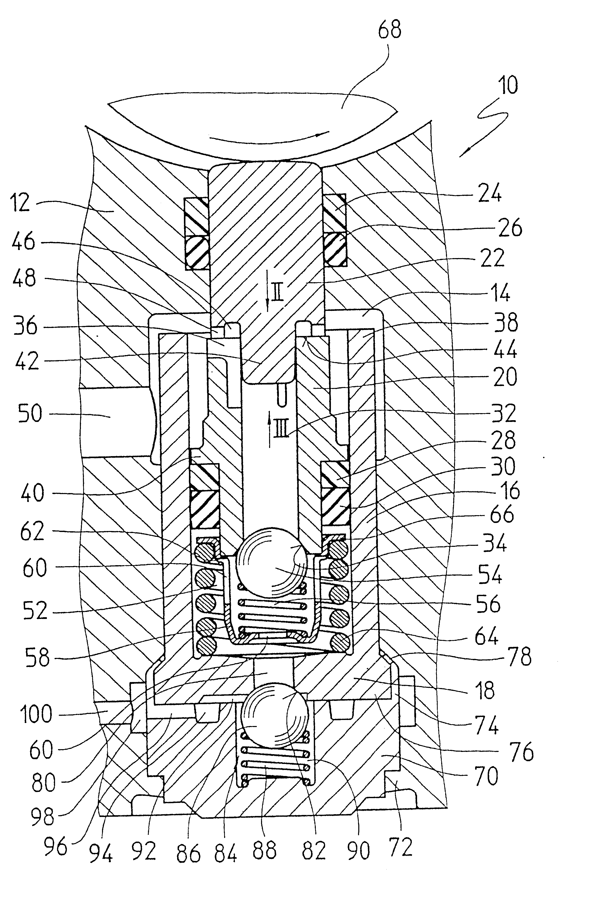
The piston pump 10 of the invention, shown in FIG. 1, is inserted into a hydraulic block 12, of which only a fraction surrounding the piston pump 10 is shown in the drawing. Other hydraulic components not shown, such as magnet valves, hydraulic reservoirs and dampers of a slip-controlled vehicle brake system, are inserted into the hydraulic block 12 and hydraulically connected by the hydraulic block 12 both to one another and to the piston pump 10. The hydraulic block 12 forms a pump housing for the piston pump 10 of the invention and will be called the pump housing 12 hereinafter.

A bush 16 is press-fitted into a stepped, continuous bore 14 in the pump housing 12. The tubular bush 16 has a bush bottom 18 that is integral with it. A two-part piston 20, 22 is axially displaceably received in the bush 16. The two-part piston 20, 22 protrudes for part of its length from the bush 16. On its part protruding from the bush 16, it is guided axially displaceably in the pump housing 12 by a sl...


PUM


Abstract

To enable economical production of a piston for a piston pump, the piston is made from a tubular deformed part and a closure plug, which is press-fitted with a protrusion into the deformed part. The piston has the advantage that the piston can be made without metal cutting in the form of deformed parts, for instance by extrusion, and hence can be produced quickly and economically.

Description

PRIOR ARTThe invention relates to a piston pump which is intended for use as a return feed pump for a slip-controlled vehicle brake system.Such piston pumps are known per se. For example, see the piston pump disclosed in German Patent Disclosure DE 40 27 794 A1. This known piston pump has a pump housing, in which a piston that can be driven to execute a reciprocating stroke motion is axially displaceably received. For fluid admission, the piston of the known piston pump has an axial bore, which extends to approximately the middle of the piston and is intersected by a transverse bore. At an orifice of the axial bore at one face end of the piston, a valve seat made by metal cutting machining is provided for a check valve, which in the known piston pump forms an inlet valve. The piston is a part made by metal-cutting machining in the form of drilling and turning on a lathe. The piston is complicated and expensive to make.ADVANTAGES OF THE INVENTIONThe piston of the piston pump of the i...

Claims


Application Information

Patent Timeline
IPC IPC(8): B60T8/40B60T13/10B60T13/16F04B53/10F04B9/02F04B53/14F04B9/04F04B53/00F04B53/12F04B1/04F04B1/00
CPCB60T8/4031B60T13/168F04B1/0408F04B1/0421F04B9/045F04B53/126F04B53/143F04B53/148F05C2225/00
Inventor MERKLEIN, DETERWEH, ANDREASHELLEBRANDT, MICHAEL
Owner ROBERT BOSCH GMBH
Why Eureka
Try Eureka