Suspension system with intrinsic safety features for aircraft powerplants

a safety feature and suspension system technology, applied in the direction of aircraft power plant components, transportation and packaging, fuselages, etc., can solve the problems of increasing the number of parts, affecting the safety of the suspension system, so as to facilitate the integration of safety features

Inactive Publication Date: 2002-11-05
SN DETUDE & DE CONSTR DE MOTEURS DAVIATION S N E C M A
View PDF32 Cites 41 Cited by
  • Summary
  • Abstract
  • Description
  • Claims
  • Application Information

AI Technical Summary

Benefits of technology

is to create an engine suspension system that easily integrates safety featur

Problems solved by technology

When the powerplant operates under certain flight conditions, in particular at takeoff, the spindle and the linkrods are subjected to co

Method used


Image

  • Suspension system with intrinsic safety features for aircraft powerplants
  • Suspension system with intrinsic safety features for aircraft powerplants
  • Suspension system with intrinsic safety features for aircraft powerplants

Examples


Embodiment Construction

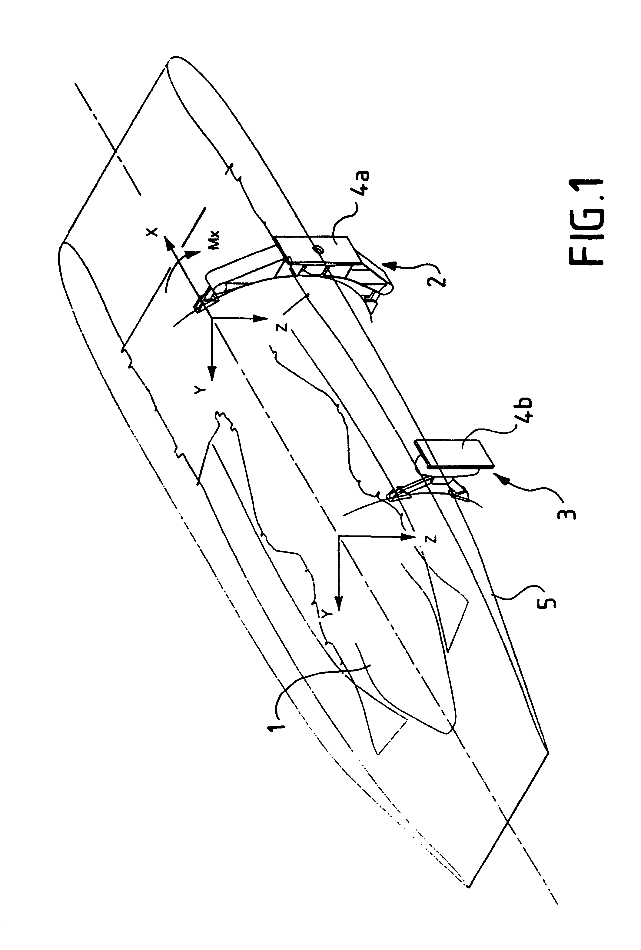
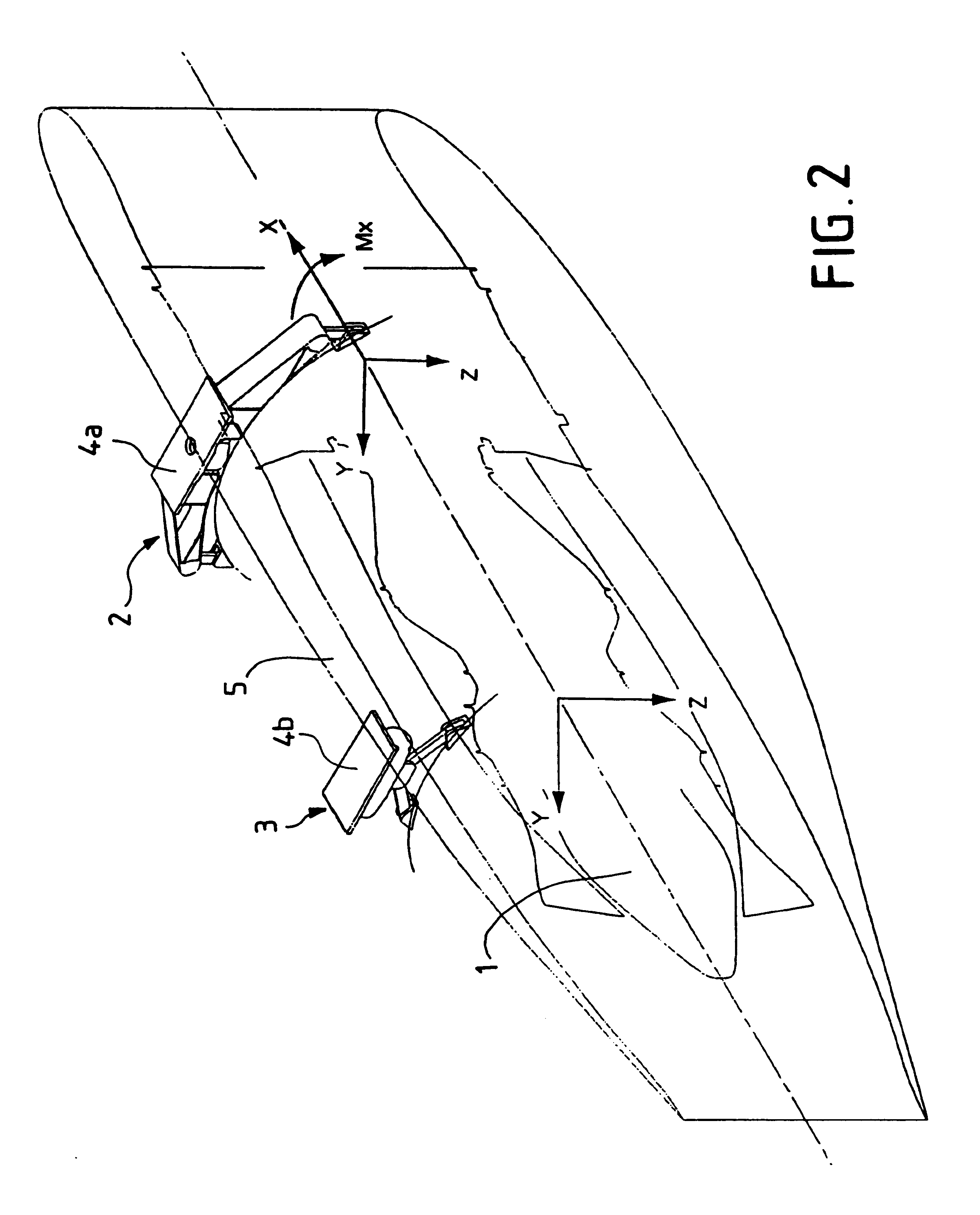
FIGS. 1 and 2 show a powerplant 1 having a longitudinal X-axis and fitted with a front suspension system 2 and a rear suspension system 3.

Each system is arranged with a front and rear bracket 4a and 4b, respectively, to affix the powerplant 1 to a truss of an aircraft frame, either to the fuselage (FIG. 1) or to the wing (FIG. 2). FIGS. 1 and 2 also show the vertical reference Z-axis and the transverse reference Y-axis. The three reference axes X, Y, Z are mutually orthogonal.

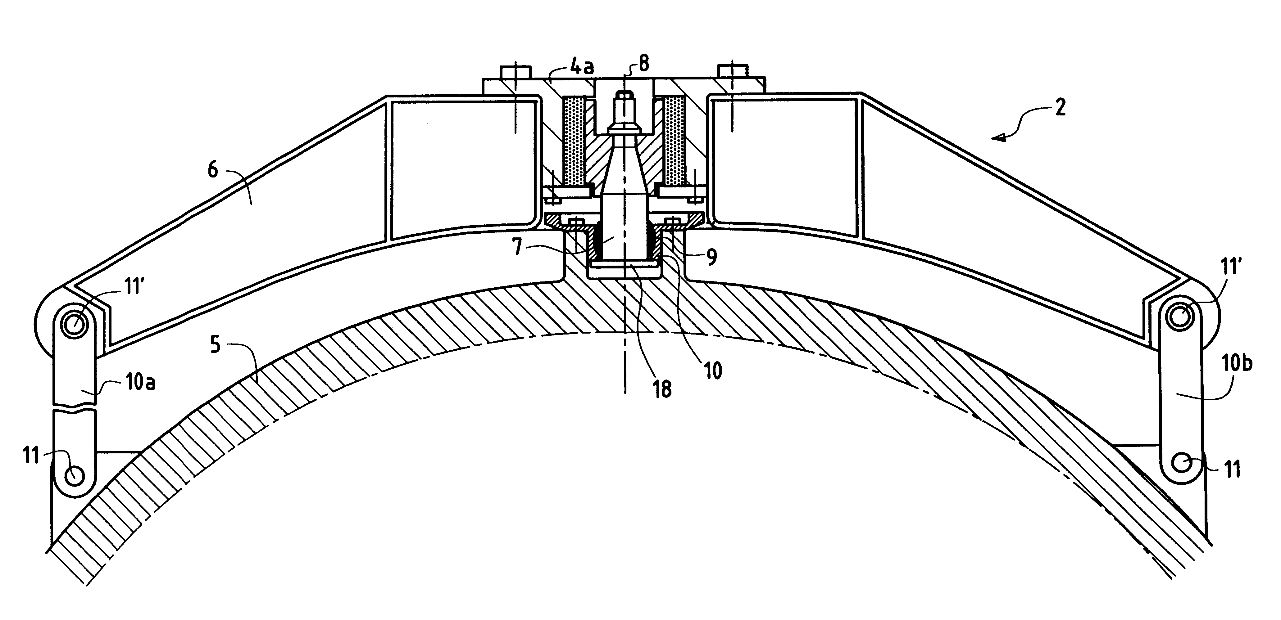
As shown in more detail in FIGS. 3 through 6, the front suspension 10 system 3 also comprises a suspension arm 6 and a spindle 7 which are rigidly joined to the bracket 4a. The Y-axis 8 of the spindle 7 is perpendicular to the longitudinal reference X-axis and coincides with the vertical Z-axis when the powerplant is suspended underneath a wing. The Y-axis 8 coincides with the transverse axis Y of the powerplant when the powerplant is attached to the fuselage.

The front suspension system 2 and the powerplant hou...


PUM


Abstract

A suspension system for an aircraft powerplant attached to an aircraft frame and having a housing. The suspension system includes a spindle mounted in a spindle support rigidly joined to the aircraft frame, a bearing cage affixed to the housing and having a bearing positioned therein, a pair of suspension arms connected to the spindle support, and a pair of lateral linkrods configured to link the housing and the suspension arms. The side surfaces of the bearing cage and the suspension arms define a clearance therebetween concentric to the Y-axis. The bearing cage is configurable along the spindle such that the bearing cage is limited to displacement relative to the longitude of the spindle while maintaining contact with the spindle.

Description

1. Field of the InventionThe invention relates to a suspension system attaching a powerplant to an aircraft frame, whether laterally to the fuselage or suspended from the wing.2. Related ArtMore specifically the present invention relates to a suspension system wherein a bearing is mounted on a bearing cage affixed to a powerplant housing. The bearing is slidable on a spindle that has an axis that is perpendicular to the powerplant axis and is mounted on a spindle support solidly joined to the airframe. Two lateral linkrods each link the housing and one of two suspension arms supported by the spindle support.Loads along the longitudinal axis are absorbed by the spindle. When the powerplant is mounted laterally to the fuselage, the spindle also absorbs vertical loads along the vertical or Z-axis, whereas the linkrods absorb the lateral loads along the Y-axis. If the powerplant is suspended underneath the wing, the spindle also absorbs the lateral loads along the Y-axis, whereas the ve...

Claims


Application Information

Patent Timeline
IPC IPC(8): B64D27/26B64D27/00B64D27/16
CPCB64D27/26B64D2027/266
Inventor COUSIN, ANTOINE EMMANUELMAZEAUD, GEORGESPICARD, JEAN-LOUIS
Owner SN DETUDE & DE CONSTR DE MOTEURS DAVIATION S N E C M A
Why Eureka
Try Eureka