Method for reducing condensation water in gas sensor arrangements

a gas sensor and condensation water technology, applied in the direction of optical radiation measurement, instruments, measurement devices, etc., can solve the problem of insufficient thermal dissipation loss of radiation sources, and achieve the effect of preventing condensation from test gas

Active Publication Date: 2006-02-16
BAYERISCHE MOTOREN WERKE AG
View PDF9 Cites 3 Cited by
  • Summary
  • Abstract
  • Description
  • Claims
  • Application Information

AI Technical Summary

Benefits of technology

[0008] The present invention is based on the idea that condensation from the test gas may be prevented, if the gas measuring chamber is heated before the measurement process, such that the wall of the gas measuring chamber assumes a temperature which lies above the dew point of the test gas. It may thus be ensured that the moisture present in the test gas cannot condense on the inner walls of the gas measuring chamber and an effect of the condensed moisture on the measurement results as well as possible damage to individual components of the gas sensor arrangement, for example by corrosion, may be prevented.

Problems solved by technology

When using narrow band radiation sources, however, it can happen that the available thermal dissipation loss of the radiation source is not sufficient to heat the inner walls of the gas measuring chamber beyond the respective dew point.

Method used


Image

  • Method for reducing condensation water in gas sensor arrangements
  • Method for reducing condensation water in gas sensor arrangements
  • Method for reducing condensation water in gas sensor arrangements

Examples


Embodiment Construction

)

[0019] The construction and the mode of operation of a gas sensor arrangement according to exemplary embodiments of the invention are to be described in more detail hereinafter with reference to the drawing figures.

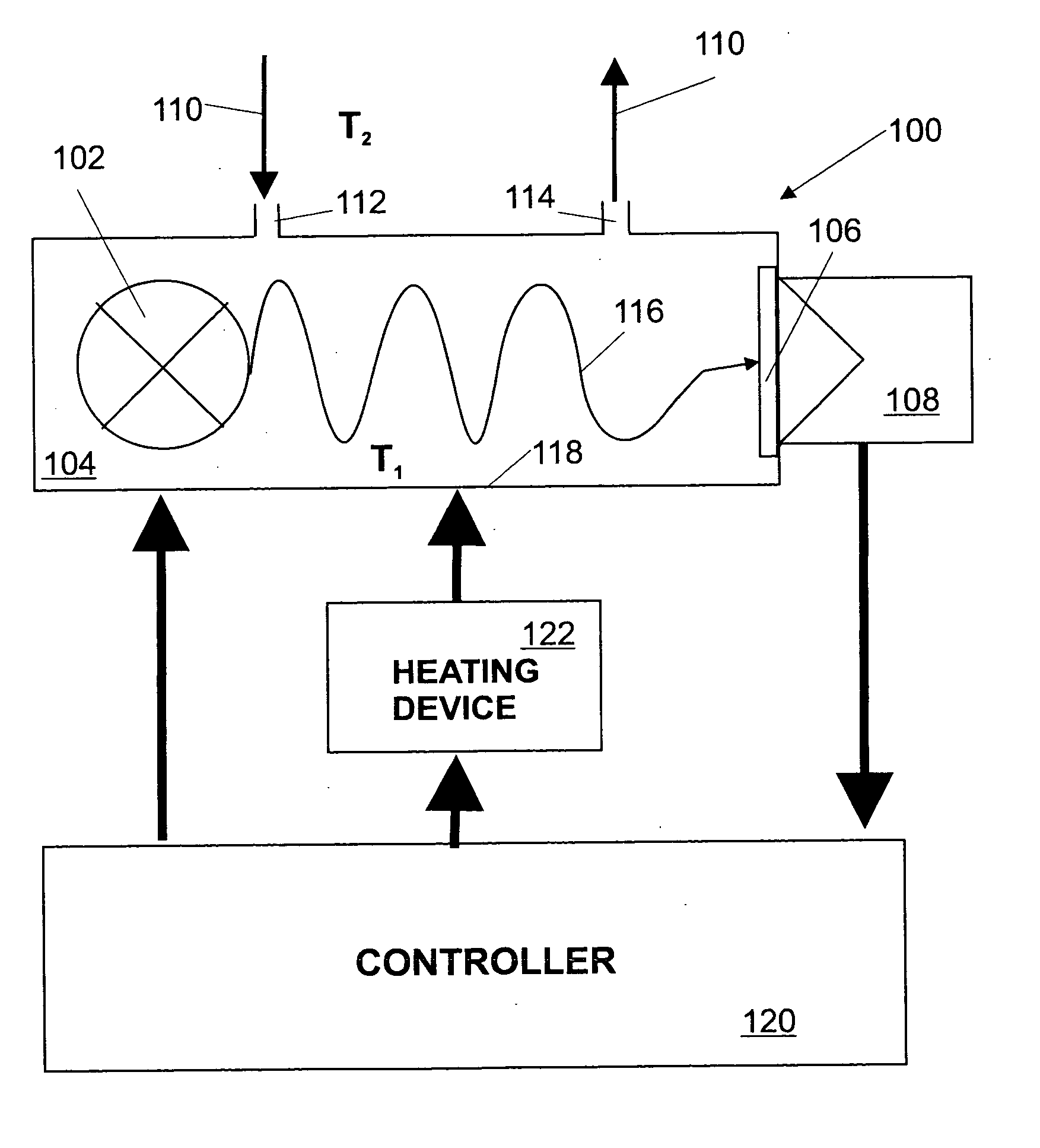
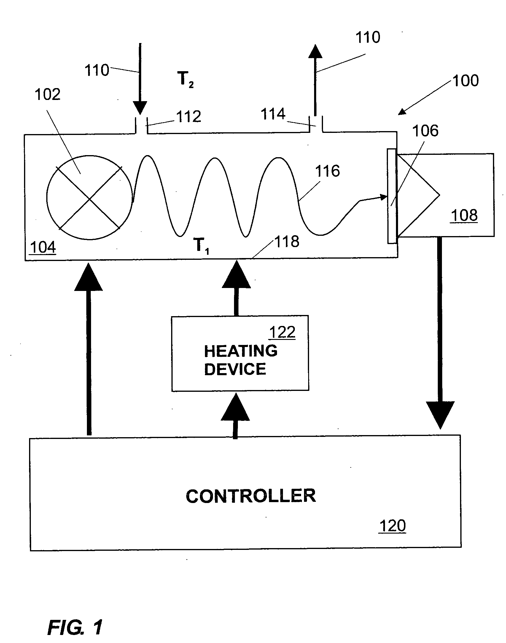
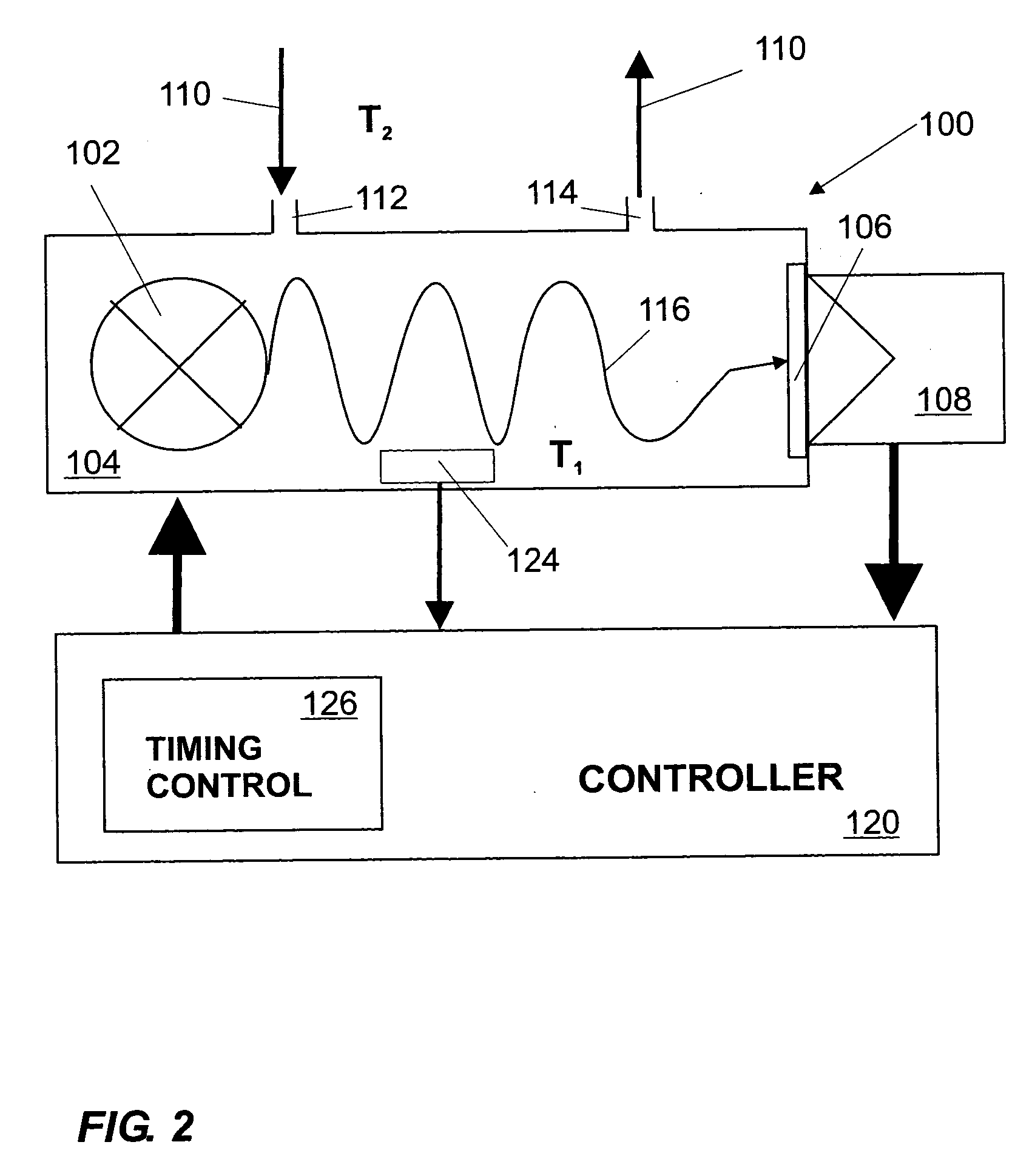
[0020] As shown in FIG. 1, a gas sensor arrangement 100 comprises a radiation source 102, in this case a broadband infrared radiation source. In principle, the gas sensor arrangement 100 shown is a so-called NDIR sensor (non-dispersive infrared sensor). The principal components, in addition to the infrared source 102, which in the simplest of cases is a lamp, are: a gas measuring chamber 104, a wavelength filter 106 and an infrared detector 108.

[0021] The test gas 110 is pumped into the gas measuring chamber 104 or diff-used therein, as symbolized by the inlets and outlets 112, 114. The gas concentration can be determined electro-optically via the absorption of a specific wavelength in the infrared range. In this connection the infrared radiation 116 emitted is conveye...


PUM


Abstract

The present invention relates to a method for measuring the presence and/or the concentration of an analyte by means of a gas sensor arrangement and to a corresponding gas sensor arrangement. The gas sensor arrangement comprises a radiation-emitting radiation source, a gas measuring chamber, which may be filled with a test gas containing at least one analyte to be measured, and at least one radiation-detecting detector device which generates an output signal as a function of the presence and/or the concentration of the analyte. In order to be able to reduce the harmful effects of condensation water, which condenses in the gas measuring chamber, the gas measuring chamber according to the invention is heated before the measurement process, such that the wall of the gas measuring chamber assumes a temperature which lies above the dew point of the test gas.

Description

FIELD OF THE INVENTION [0001] The present invention relates to a method for measuring the presence and / or the concentration of an analyte by means of a gas sensor arrangement and to an appropriate gas sensor arrangement. BACKGROUND [0002] Gas sensor arrangements comprising a radiation-emitting radiation source, a gas measuring chamber, which may be filled with a test gas containing at least one analyte to be measured, and at least one radiation-detecting detector device which generates an output signal as a function of the presence and / or the concentration of the analyte are known for the detection of a wide variety of analytes, for example methane or carbon dioxide. Conventional gas sensors, as they are disclosed, for example, in EP 0 616 207 A2, WO 00 / 55603 A1 or DE 199 251 96 C2, are based on the property of many polyatomic gases of absorbing radiation, in particular in the infrared wavelength region. Said absorption occurs in a wavelength characteristic of the respective gas, fo...

Claims


Application Information

Patent Timeline
Patent Type & Authority Applications(United States)
IPC IPC(8): G01J5/02
CPCG01N21/15G01N2021/158G01N21/3504
Inventor FISCHER, JOERGFORLENZA, MARCOFRODL, ROBERTMINUTH, RUDISTRAUB, KUNOTILLE, THOMAS
Owner BAYERISCHE MOTOREN WERKE AG
Why Eureka
Try Eureka