Attachment structure of electronic component to circuit board and clip used in attachment of the electronic component

a technology of electronic components and attachment structures, which is applied in the direction of printed circuit non-printed electric components, electrical apparatus casings/cabinets/drawers, instruments, etc., can solve the problems of inferior attachment structure in workability and economic attachment, increased treatment cost, and inability to meet the needs of electronic components

Inactive Publication Date: 2002-12-03
CALSONIC KANSEI CORP
View PDF3 Cites 3 Cited by
  • Summary
  • Abstract
  • Description
  • Claims
  • Application Information

AI Technical Summary

Benefits of technology

It is also an object of the present invention to carry out the soldering work for a connection circuit in the lower surface (back surface) of the rigid circuit board by use of a flow soldering tank so that the workability and economy of the soldering are enhanced.
Thus, according to this attachment structure, the attachment of the electronic component to the rigid circuit board can be ensured by the engagement force of the clips and the soldering between the clips and the lands provided on the rigid circuit board. As a result, the workability in attaching the electronic component to the rigid circuit board is improved on a large scale.
Thus, by using such a clip to fix an electronic component to a rigid circuit board, the rigid circuit board and the electronic component can be fixedly positioned by one touch. In addition, by fixing the clip to the rigid circuit board by soldering, it is possible to ensure the connection among the clip, the electronic component, and the circuit board. Thus, the workability in attachment of the electronic component to the rigid circuit board becomes excellent.

Problems solved by technology

From such a point, the attachment structure is inferior in the workability and economy in attachment of the instrument movement.
At this time, however, there arises a problem that solder balls repelled by the head portions of the attachment screws 13 adhere to a circuit portion of the rigid circuit board so as to cause an electric connection failure (short-circuit due to a solder bridge or the like).
However, it is not practical because the treatment cost increases when surface treatment is given to the respective head portions of the attachment screws 13 so as to make solder easy to adhere to the head portions.
Therefore, it takes much time for soldering so that the assembling productivity deteriorates.
However, since the engagement nail is made of resin, the resin engagement nail deforms due to the heat generated in the flow soldering.
However, the high heat resistance resin is expensive in general, which increases the manufacturing cost thereof, and therefore it is not practical.

Method used


Image

  • Attachment structure of electronic component to circuit board and clip used in attachment of the electronic component
  • Attachment structure of electronic component to circuit board and clip used in attachment of the electronic component
  • Attachment structure of electronic component to circuit board and clip used in attachment of the electronic component

Examples


Embodiment Construction

The present invention will be described below in detail with respect to an embodiment illustrated in the drawings.

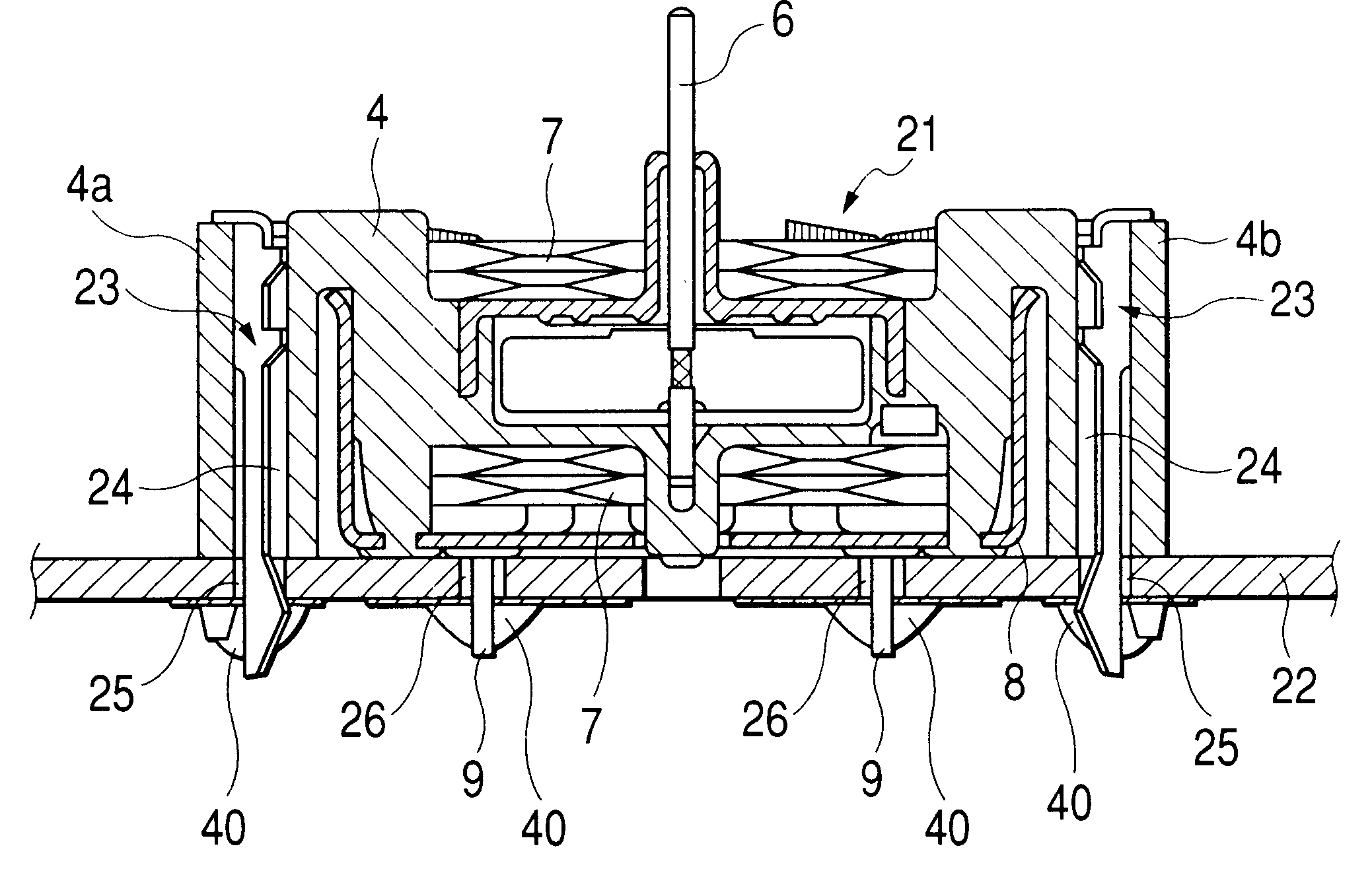
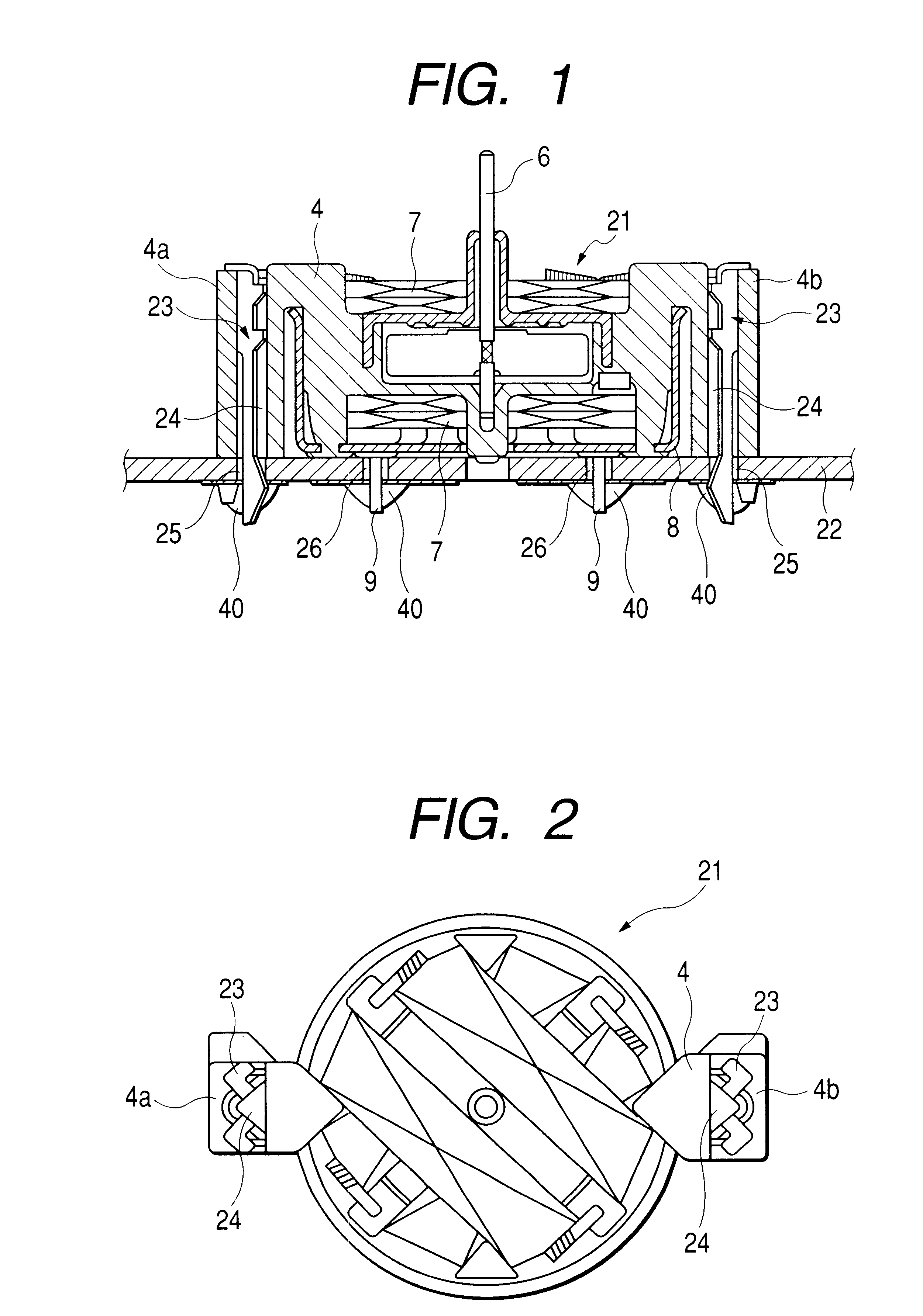
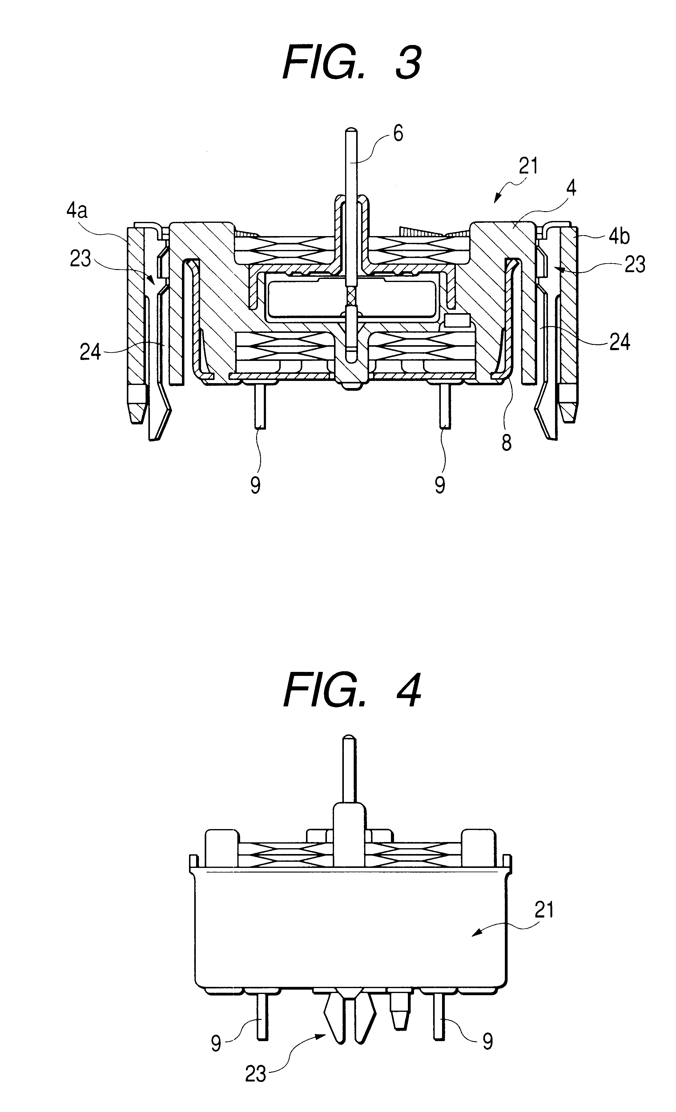
FIG. 1 is an explanatory view showing the condition that an instrument movement 21 as an electronic component has been attached to a rigid circuit board 22 by use of clips 23. The electronic component 21 for use in the attachment structure according to the present invention is not limited to the instrument movement. In addition, the illustrated internal configuration of the instrument movement is substantially the same as that of the instrument movement described in the conventional art example. Therefore, constituent parts the same as those in the conventional art example are referenced correspondingly, and the description of the constituent parts will be omitted.

In a resin housing 4 of the instrument movement 21 according to this embodiment, arm portions 4a and 4b face with each other so that a pointer shaft 6 to be the center of the instrument movement 21 is located b...


PUM


Abstract

An attachment structure is constituted by: a rigid circuit board having a suitable circuit pattern formed on its back surface, having one or a plurality of attachment holes for mounting an electronic component on the rigid circuit board, and having soldering lands provided at the circumferential edges of the attachment holes on the back surface of the rigid circuit board; an electronic component having one or more clip pass-through holes located in positions corresponding to the attachment holes on the surface of the rigid circuit board so that the attachment holes and the clip pass-through holes agree with each other on the surface of the rigid circuit board; and clips which can be subjected to soldering, the clip penetrating the clip pass-through holes and the attachment holes from above the electronic component so that the rigid circuit board and the electronic component are positioned fixedly by the clips.

Description

1. Field of the InventionThe present invention relates to an attachment structure to a circuit board, for example, for attaching an electronic component such as an instrument movement or the like to a rigid circuit board, and a clip used in the attachment. Particularly, the present invention relates to an attachment structure of an electronic component to a circuit board, by which the workability and economy in attachment of an attachment member to a rigid circuit board can be enhanced, and a clip for use in the attachment.2. Description of the Related ArtFor example, a conventional structure with which an instrument movement (electronic component) for use in assembling an on-vehicle instrument apparatus is attached to a rigid circuit board of the on-vehicle instrument apparatus will be described with reference to FIG. 10. The reference numeral 1 represents a rigid circuit board. A predetermined printed pattern circuit 2 is formed in the lower surface of the rigid circuit board 1.Th...

Claims


Application Information

Patent Timeline
Patent Type & Authority Patents(United States)
IPC IPC(8): G01P1/00G01R7/00G01R7/06H05K7/12H05K3/30H05K1/18H05K5/00H05K5/04H05K5/06H05K7/14
CPCG01P1/00G01R7/06G01P1/07H05K7/12H05K3/301
Inventor TAKAHASHI, HIDEYUKIHINO, SHOJI
Owner CALSONIC KANSEI CORP
Why Eureka
Try Eureka