Cache flush apparatus and computer system having the same

a technology of cache memory and flushing apparatus, which is applied in the direction of memory adressing/allocation/relocation, redundancy hardware error correction, instruments, etc., can solve the problems of requiring a major modification of the present cache controller design, the inefficiency of a cache flush is apparently more critical, and the frequentity of cache misses during normal data processing. achieve the effect of accelerating the creation of checkpoints and increasing system performan

Inactive Publication Date: 2002-12-03
KK TOSHIBA
View PDF9 Cites 76 Cited by
  • Summary
  • Abstract
  • Description
  • Claims
  • Application Information

AI Technical Summary

Benefits of technology

According to the first aspect of the present invention, the address of data held in a dirty block is stored in an entry of the selected region of the update address storage means. When a processor updates some data and as a result the state of a cache block turns dirty, the memory address MU is captured and stored in an empty entry of the selected region of the update address storage means. When a write-back of data from a dirty block occurs (which means the state of the cache block turns "shared"), the update address is removed from the update address storage means. The reason why the update address storage means is divided into regions and the update address registering means and the update address removing means select a region is that the removal operation can be accelerated by reducing the number of entries which must be examined.
In addition to the above computer system for periodically acquiring checkpoints, the cache flush apparatus according to the present invention can be applied to a duplex computer system in which the primary computer alternately continues normal data processing and sends its checkpoint image to the secondary computer and when a fault occurs within the primary computer, the secondary computers takes over the normal data processing. The cache flush means of the cache flush apparatus accelerates the checkpoint creation of the primary computer.

Problems solved by technology

Therefore, when a cache flush has been performed by executing the "wbinvd" instruction as a part of checkpoint creation, cache misses occur very frequently during the normal data processing which follows the checkpoint creation.
Therefore, the inefficiency of a cache flush is apparently more critical than the case of Intel Pentium processor.
However, this method has a critical disadvantage that it requires a major modification of the present cache controller design, which is too costly.

Method used


Image

  • Cache flush apparatus and computer system having the same
  • Cache flush apparatus and computer system having the same
  • Cache flush apparatus and computer system having the same

Examples


first embodiment

(First Embodiment)

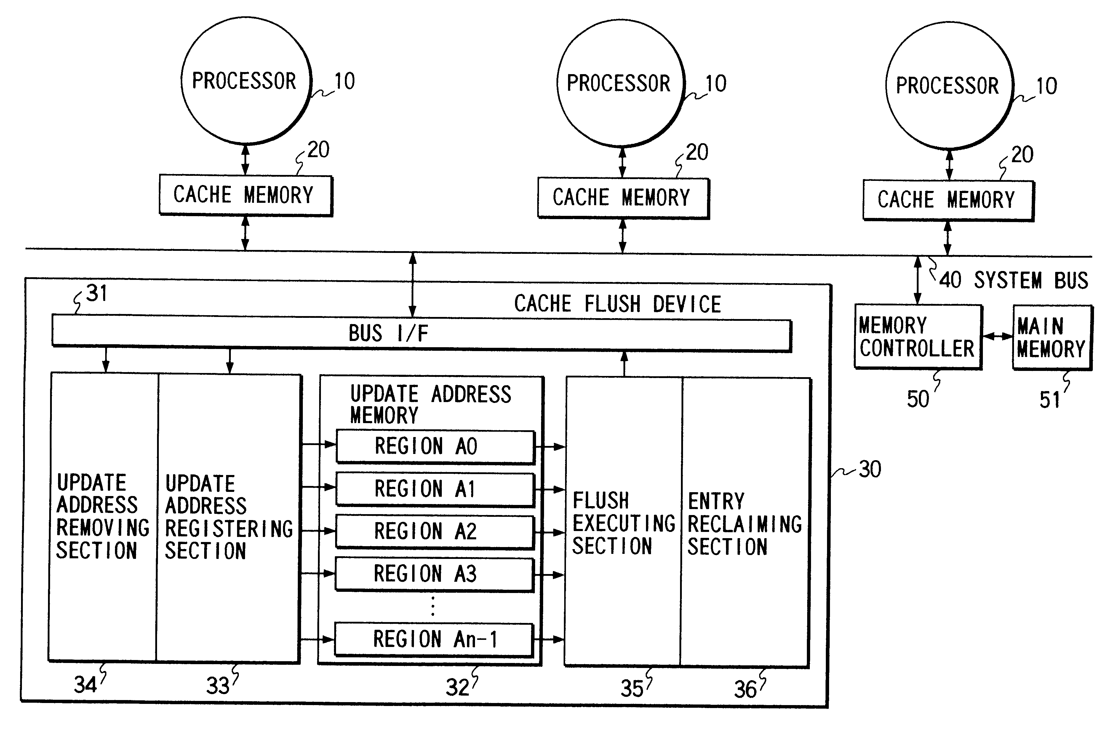
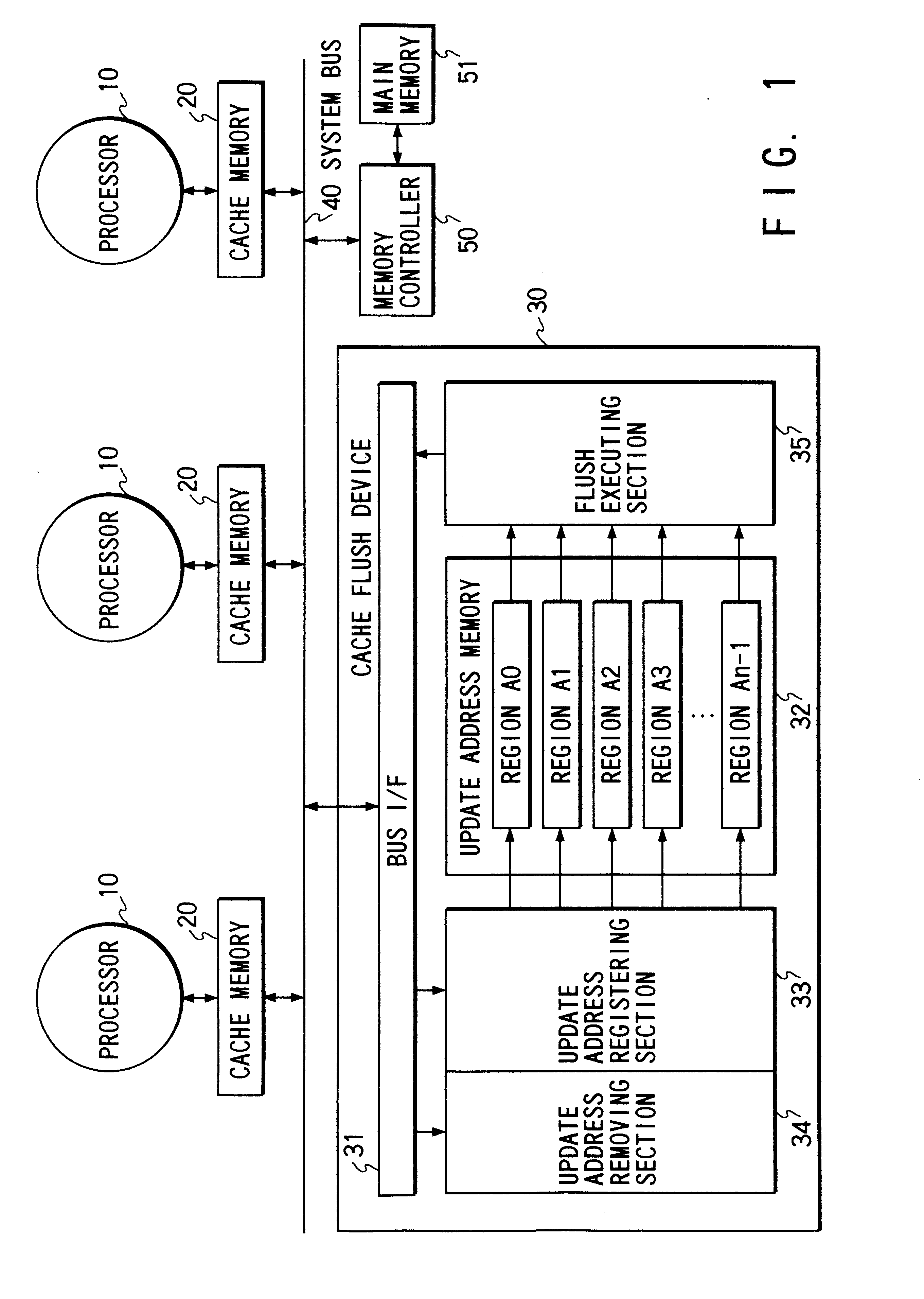
FIG. 1 is a block diagram showing the configuration of a computer system according to the first embodiment of the present invention. Each processor 10 has its own copy-back type cache memory 20 with a cache coherency mechanism and is connected to a system bus 40. In a case where the configuration of the cache memory 20 is two level (namely comprises primary and secondary cache memories) or more, the cache memory according to this embodiment means the cache memory nearest to the system bus 40. In case where a cache memory comprises an instruction cache memory and a data cache memory, the cache memory according to this embodiment means the data cache memory. The system bus 40 according to this embodiment has 32 bit width.

A cache flush device 30 and a memory controller 50 for a main memory 51, are connected to the system bus 40. The cache flush device 30 includes a system bus interface 31, an update address memory 32 (consisting of regions A.sub.0 to A.sub.n-1), an up...

second embodiment

(Second Embodiment)

A second embodiment of the present invention will now be described. FIG. 16 shows the structure of a computer system according to the second embodiment of the present invention. The structure of the computer, to which the cache flush device 30 is applied, is the same as that according to the first embodiment.

The cache flush device 30 comprises the system bus interface 31, update address memory 32 (regions A.sub.0 to A.sub.n-1), update address registering section 33, flush executing section 35 and an entry reclaiming section 36.

The update address memory 32 is composed of n regions (regions A.sub.0 to A.sub.n-1) for storing addresses of all of the dirty blocks. In this embodiment, the addresses of all the dirty blocks are stored in the update address memory 32. However, the update address memory 32 may also hold addresses of the associated cache block which is not dirty. The reason for this is that the update address removing section 34 of the first embodiment is om...

third embodiment

(Third Embodiment)

A third embodiment of the present invention will now be described.

FIG. 21 shows the structure of the computer system according to the third embodiment. The cache flush device 30 is applied to the same computer as of the first and second embodiments.

The cache flush device 30 comprises a system bus interface 31, update address memory 32 (regions A.sub.0 to A.sub.n-1), update address registering section 33, update address removing section 34, flush executing section 35 and entry reclaiming section 36.

The update address memory 32, the update address registering section 33, the flush executing section 35 and the entry reclaiming section 36 are the same as those according to the second embodiment.

The difference from the second embodiment is that the update address removing section is added like the first embodiment. While the update address removing section of the first embodiment, when a write-back bus command is observed, always seeks and clears the entry having the ad...


PUM


Abstract

Addresses of all of dirty blocks of a cache memory are, by an update address registering section, stored in one of plural regions of an update address memory. When a certain cache block is brought to a dirty state and then suspended from the dirty state, the update address removing section removes the address from the region. When cache flush is performed, a flush executing section sequentially fetches the addresses of the dirty blocks from each region to issue, to the system bus, a command for writing-back data indicated by the address into the main memory so that the contents of all of the a dirty block are written-back into the main memory. Therefore, the cache flush apparatus according to the present invention is able to shorten time required to perform the cache flush procedure and to improve the performance of a computer system having the cache flush apparatus.

Description

BACKGROUND OF THE INVENTIONThis application is based on Japanese Patent Application No. 8-238,157, filed Sep. 9, 1996, the content of which is incorporated herein by reference.The present invention relates to a cache flush apparatus for a cache memory having a snoop mechanism for maintaining data coherency and a fault tolerant computer system having the cache flush apparatus.In general, a modern high-speed processor has a cache memory for temporarily holding data required by the processor in order to reduce the effective memory access latency. A cache memory holds data and the memory address at which the data is read out in a fixed size data storage unit called a cache block.In a computer (more specifically a multi-processor computer) having a plurality of processors each of which has its own cache memory, a snoop mechanism is usually used to maintain data coherency among the cache memories. A snoop mechanism monitors the system bus to detect bus commands and if a bus command which ...

Claims


Application Information

Patent Timeline
Patent Type & Authority Patents(United States)
IPC IPC(8): G06F12/08G06F11/14G06F11/20G06F12/00
CPCG06F11/2041G06F11/2043G06F12/0804G06F11/1407G06F12/0831G06F12/08
Inventor MASUBUCHI, YOSHIOKANO, TAKUYASAKAI, HIROSHI
Owner KK TOSHIBA
Why Eureka
Try Eureka