Vapor driven aerosol generator and method of use thereof

a generator and aerosol technology, applied in the field of aerosol generators, can solve the problems of inability to deliver material at such high flow rates, most known aerosol generators are incapable of generating aerosols having an average mass median particle diameter less than 2 microns, and the effect of reducing the number of aerosol generators

Inactive Publication Date: 2002-12-10
PHILIP MORRIS USA INC
View PDF216 Cites 103 Cited by
  • Summary
  • Abstract
  • Description
  • Claims
  • Application Information

AI Technical Summary

Problems solved by technology

Most known aerosol generators are incapable of generating aerosols having an average mass median particle diameter less than 2 microns.
Most known aerosol generators suited for delivering medicated material are incapable of delivering material at such high flow rates while maintaining a suitable average mass median particle diameter.
In addition, most known aerosol generators deliver an imprecise amount of aerosol compared with the amount of aerosol that is intended to be delivered.
However, since these aerosol generators employ heat-generating systems, heat resistive material and, in some cases, various control devices, pumps and valves, the manufacture and assembly of such aerosol generators can be complicated and expensive.

Method used


Image

  • Vapor driven aerosol generator and method of use thereof
  • Vapor driven aerosol generator and method of use thereof

Examples


first embodiment

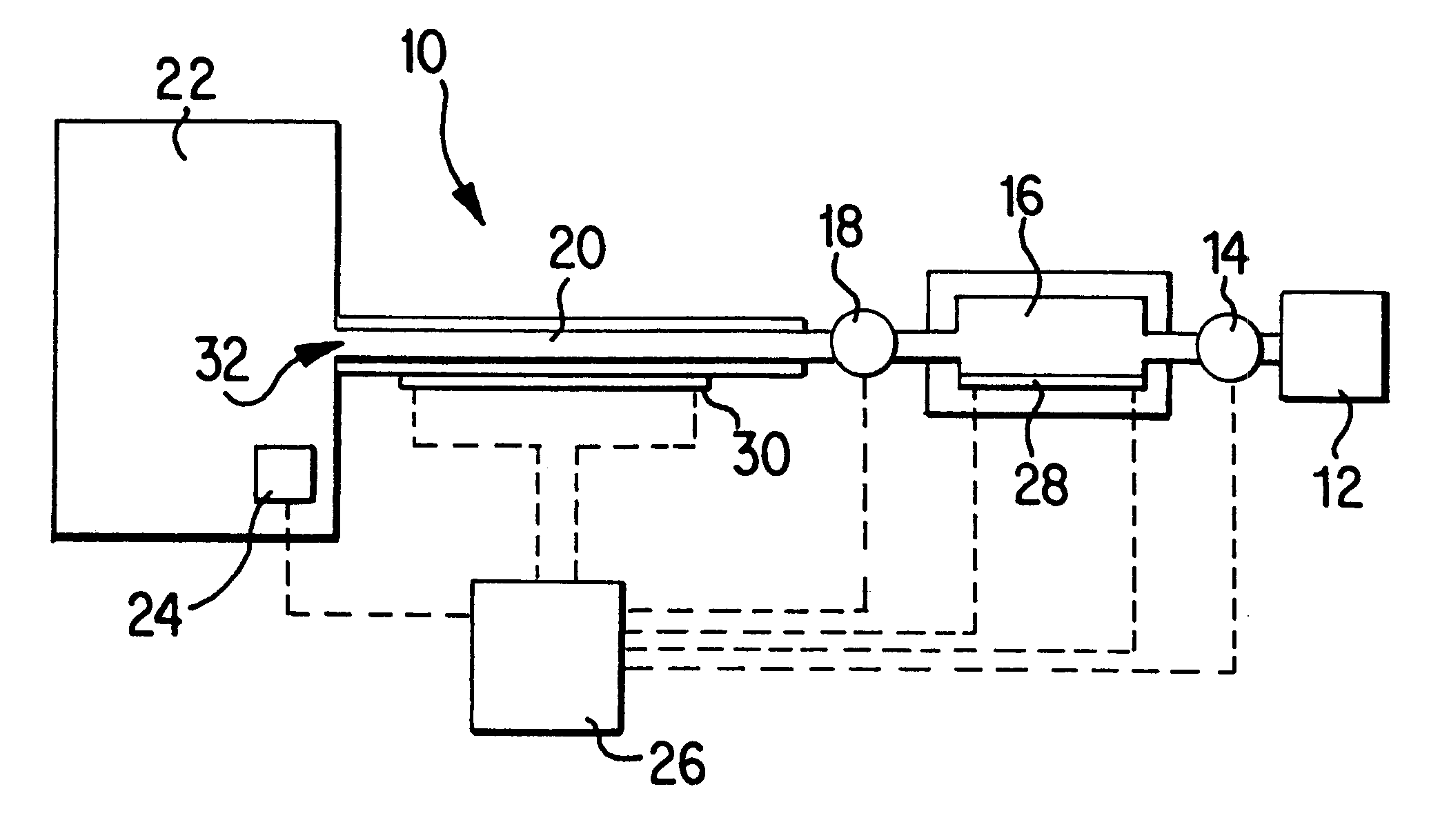
FIG. 2 shows a top cutaway view of a vapor driven aerosol generator 40 in accordance with another embodiment of the invention. As shown, the aerosol generator 40 includes a fluid supply 42, a chamber 44, a passage 46, a preheater 48 and a main heater 50. The preheater 48 can be arranged on one side of the chamber 44 such that fluid in the chamber 44 is heated to form a vapor bubble which expands and drives the remaining fluid in the chamber 44 into the passage 46. If desired, an additional preheater 52 can be provided in the chamber 44 in order to provide additional heating of the fluid. The heaters 48, 52 extend horizontally along bottom and top walls of the chamber 44. The heaters 48, 50, 52 are preferably thin films of resistance heating material. In order to pass electrical current through the heaters, the heaters can be in electrical contact with suitable electrical contacts 54. A suitable power source such as a battery can be used to deliver sufficient direct current to the co...

third embodiment

FIG. 3 shows a side view of a vapor driven aerosol generator in accordance with the invention. As shown, the aerosol generator 60 includes a fluid supply 62, a chamber 64, a passage 66, a preheater 68 and a main heater 70. The aerosol generator 60 can be formed from solid state components such as layers 72, 74, 76 of metal, organic or ceramic material such as a polymer material or ceramic material. If desired, layers 74 and 76 can comprise a single layer which has been machined or etched to form the passage 66 and the chamber 64. Alternatively, one or more layers can be interposed between the layers 74 and 76 so as to form the passage 66 and the chamber 64. As in the case of the embodiment shown in FIG. 2, the heaters 68, 70 can be supplied power by contacts 78. The heater 68 is arranged to extend vertically along an inner sidewall of the chamber 64. In arrangements wherein the heater contacts the fluid, it is desirable to coat the heater with a material which is nonreactive with th...


PUM


Abstract

An aerosol generator includes a fluid supply which supplies fluid to a fluid passage, a main heater which heats the fluid into a gaseous state and a preheater which delivers a volume of fluid to the main heater. The preheater can be located in or adjacent a metering chamber which receives a predetermined volume of fluid, the preheater heating a portion of the fluid so as to form a vapor bubble which ejects the remaining fluid from the chamber. An outlet of the aerosol generator is arranged to receive the volatilized fluid formed by the main heater and direct the volatilized fluid out of the fluid passage. The aerosol generator can be used to generate aerosols containing medicated materials.

Description

1. Field of the InventionThe present invention relates generally to aerosol generators and, more particularly, to vapor driven aerosol generators. The aerosol generators of the invention are able to generate aerosols without requiring the use of compressed gas propellants. The present invention also relates to methods for generating an aerosol. The present invention has particular applicability to the generation of aerosols containing medicated material.2. Description of the Related ArtAerosols are gaseous suspensions of fine solid or liquid particles and are useful in a wide variety of applications. For example, medicated liquids and powders may be administered in aerosol form. Such medicated aerosols include, for example, materials which are useful in the treatment of respiratory ailments, in which case the aerosols may be inhaled into a patient's lungs. Aerosols may also be used in non-medicinal applications including, for example, dispensing air fresheners and insecticides and d...

Claims


Application Information

Patent Timeline
Patent Type & Authority Patents(United States)
IPC IPC(8): B05B17/04B05B7/16B05B9/00A61M11/04A61M16/00
CPCA61M11/041B05B7/1686B05B9/002B05B17/04A61M11/042A61M15/025A61M2016/0039A61M11/007
Inventor NICHOLS, WALTER A.
Owner PHILIP MORRIS USA INC
Why Eureka
Try Eureka