Fuel supply system for an internal combustion engine

a fuel supply system and internal combustion engine technology, applied in the direction of liquid fuel feeders, machines/engines, electric control, etc., can solve the problems of reducing the service life and avoiding reliability, and achieve the effect of adequate heat dissipation

Inactive Publication Date: 2005-01-11
ROBERT BOSCH GMBH
View PDF7 Cites 23 Cited by
  • Summary
  • Abstract
  • Description
  • Claims
  • Application Information

AI Technical Summary

Benefits of technology

The fuel delivery system according to this invention has the advantage over the prior art that with the aid of the coolant medium flow, the high-pressure fuel pump can be kept at a temperature level which is below a critical operating temperature of the high-pressure fuel pump. To that end, one or more suitable coolant conduits should be provided, which furnish an appropriate coolant medium flow, which assures adequate heat dissipation, to the high-pressure fuel pump.
However, it is especially expedient if a fan is associated with the at least one coolant conduit, for generating the cooling air flow through the coolant conduit; preferably, the fan is controllable as a function of the temperature of the high-pressure fuel pump and the critical operating temperature. In this way, the cooling air flow can be controlled independently of the range of use of the engine in such a way that suitable cooling of the high-pressure fuel pump can always be achieved.
If the fuel delivery system of the invention, in addition to the coolant media for the high-pressure fuel pump, has a reversible or variable pressure regulator device, then by means of a suitably highly set pilot pressure, the critical operating temperature of the high-pressure fuel pump can be increased so far that cooling of the high-pressure fuel pump, with the aid of the cooling air flow carried purposefully through the coolant conduit or coolant conduits, which stream is optionally generated with the aid of a preferably controllable fan, is adequate under all operating conditions of the engine.
By the cooling, provided according to the invention, of the high-pressure fuel pump with a separate coolant medium, vapor bubble development in the high-pressure fuel pump can be prevented, so that cooling of the high-pressure fuel pump by means of a fuel scavenging flow, which always requires a return line to the fuel tank, can be avoided. Omitting such a fuel return line not only simplifies the entire layout of the fuel delivery system but also increases safety in the case of a dangerous collision. Besides, unnecessary heating of the fuel in the fuel tank by the fuel scavenging flow that would be heated in the high-pressure fuel pump is avoided, resulting in reduced vaporization losses in the fuel tank and thus relieving the activated charcoal filters and tank venting system.
By using coolant water, and especially by using a partial stream of coolant water that is derived from the forward flow part of the cooling system of the engine, that is, downstream of the engine radiator, cooling of the high-pressure fuel pump can be improved still further.
To assure safe operation of the high-pressure fuel pump even in extreme cases, expediently at least two coolant conduits are provided, of which one delivers air and the other water as coolant medium to the high-pressure fuel pump.

Problems solved by technology

However, a limitation of the temperature of the high-pressure fuel pump is effected at best only by a certain cooling by means of the fuel flow through the high-pressure fuel pump, so that it cannot reliably be prevented that the high-pressure fuel pump will heat up enough that its temperature exceeds the critical operating temperature, that is, the temperature at which, for a given pilot pressure, fuel vapor bubble development begins.
However, the fuel feed pump would be stressed considerably by such an operating mode, which would reduce its service life.

Method used


Image

  • Fuel supply system for an internal combustion engine
  • Fuel supply system for an internal combustion engine
  • Fuel supply system for an internal combustion engine

Examples


Embodiment Construction

In the various drawing figures, components corresponding to one another are identified by the same reference numerals.

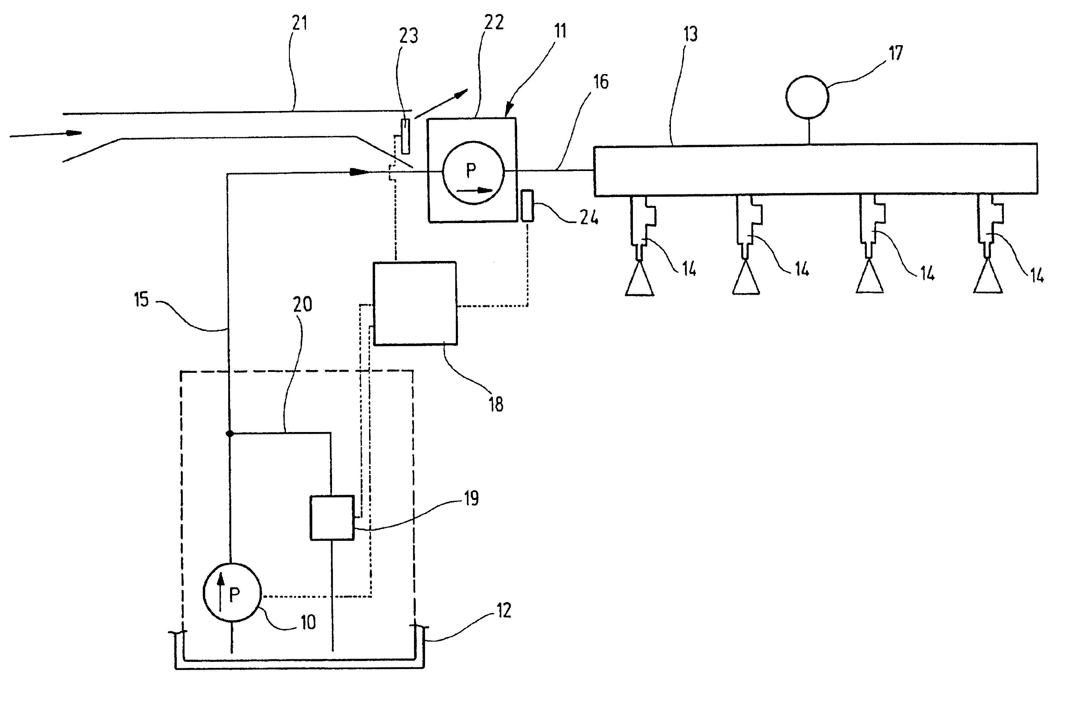
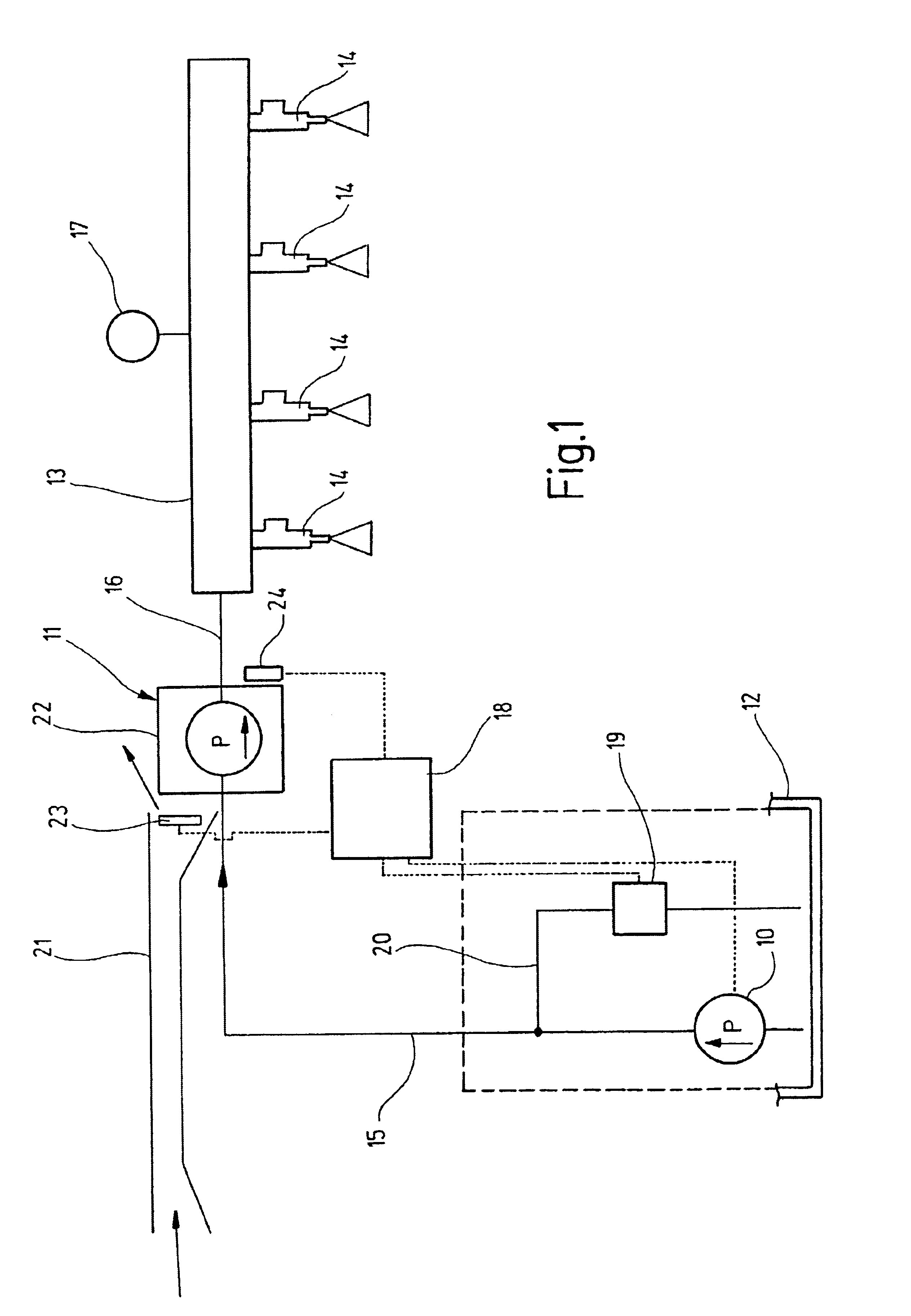
As FIG. 1 shows, a fuel delivery system of the invention has a fuel feed pump 10 and a high-pressure fuel pump 11, in order to furnish fuel from a fuel tank 12 via a pressure line system 13 to one or more injection valves 14 of an internal combustion engine. In the exemplary embodiment shown, the assumption is a four-cylinder internal combustion engine, in which each combustion chamber is assigned one injection valve, which injects fuel either directly into the combustion chamber or into its intake region.

The fuel feed pump 10, which is driven in a manner not shown in detail by an electric motor, has its compression side in communication, via a pressure line 15, with a low-pressure side of the high-pressure pump 11. The output or high-pressure side of the high-pressure pump 11 is connected via a further pressure line 16 to the pressure line system 13, to which a pres...


PUM


Abstract

A fuel delivery system for an internal combustion engine, having a fuel feed pump, which delivers fuel which is at pilot pressure to a high-pressure fuel pump that communicates on the high-pressure side with at least one injection valve, in order to deliver fuel at high pressure to the injection valve or valves. To prevent vapor bubble development in the high-pressure fuel pump, which impairs its pumping capacity and pressure generation, a coolant medium flow can be delivered to the high-pressure fuel pump via at least one coolant conduit, in order to keep the temperature (THDP) of the high-pressure fuel pump below a critical operating temperature (Tk1).

Description

BACKGROUND OF THE INVENTION1. Field of the InventionThe invention relates to a fuel delivery system for an internal combustion engine for delivering fuel at high pressure to the injector valves of the engine.2. Brief Description of the Prior ArtFrom German Patent Disclosure DE 195 39 885 A1, a fuel delivery system for an internal combustion engine is already known which has a fuel feed pump and connected in series with it a high-pressure fuel pump, so that fuel at high pressure can be furnished from the high-pressure side of the high-pressure fuel pump, via a pressure line, a reservoir and valve lines, to injection valves, each of which injects fuel directly into one of the combustion chambers of the engine. The fuel feed pump, whose outlet side communicates with the low-pressure side of the high-pressure fuel pump via a pressure line, furnishes fuel that is at pilot pressure to the high-pressure fuel pump.To keep the pilot pressure in the pressure line at a desire value, a pressure...

Claims


Application Information

Patent Timeline
Patent Type & Authority Patents(United States)
IPC IPC(8): F02M63/02F02M63/00F01P3/12F01P1/06F01P3/00F01P1/00F02M55/00F02M53/00F02M37/20F01P5/02F01P7/16F01P7/14F02M37/00F02D41/02F02D45/00F02M55/02
CPCF01P1/06F01P3/12F02M63/0225F02M37/20F02M53/00F02M55/00F01P5/02F01P7/16F02M55/007F01P2025/08
Inventor JOOS, KLAUSWOLBER, JENSFRENZ, THOMASBOCHUM, HANSJOERGAMLER, MARKUS
Owner ROBERT BOSCH GMBH
Why Eureka
Try Eureka