Electric junction box

a junction box and electric technology, applied in the direction of indirect heat exchangers, lighting and heating apparatus, transportation and packaging, etc., can solve the problems of harming the control circuit elements mounted on the control circuit board, the space for the fins needs to be reserved, etc., to achieve adequate heat dissipation, increase the surface area, and quick dissipation the effect of hea

Inactive Publication Date: 2008-02-19
SUMITOMO WIRING SYST LTD
View PDF35 Cites 22 Cited by
  • Summary
  • Abstract
  • Description
  • Claims
  • Application Information

AI Technical Summary

Benefits of technology

[0008]The present invention is provided to address the above described problems and problems in the prior art. An object of the present invention is to provide a heat sink that provides high space efficiency and good heat dissipation.
[0012]According to the present invention, the thermal diffusion portions having one of convex and concave shapes are provided on the surface of the heat sink. The structure increases a surface area of the heat sink compared to a flat surface with no concavity or convexity, thus quickly dissipating the heat to the exterior through the surface of the heat sink. The planar heat sink is capable of providing adequate heat dissipation without fins, thereby enhancing space efficiency and ensuring heat dissipation simultaneously.
[0013]According to the present invention, the heat sink is provided with the thermal diffusion portions throughout the plate surface. The structure increases a surface area of the heat sink compared to a configuration in which the thermal diffusion portions are provided to only a portion of the surface, thus improving heat dissipation. Furthermore, the heat dissipation is provided on the entire plate surface of the heat sink, thereby preventing local heat buildup in the circuitry.

Problems solved by technology

The construction of the prior art described above, however, has the drawback that space for the fins needs to be reserved.
Insufficient dissipation of the heat from the circuitry, however, may harm control circuit elements mounted on the control circuit board.

Method used


Image

  • Electric junction box
  • Electric junction box
  • Electric junction box

Examples


Embodiment Construction

[0022]The particulars shown herein are by way of example and for purposes of illustrative discussion of the embodiments of the present invention only and are presented in the cause of providing what is believed to be the most useful and readily understood description of the principles and conceptual aspects of the present invention. In this regard, no attempt is made to show structural details of the present invention in more detail than is necessary for the fundamental understanding of the present invention, the description is taken with the drawings making apparent to those skilled in the art how the forms of the present invention may be embodied in practice.

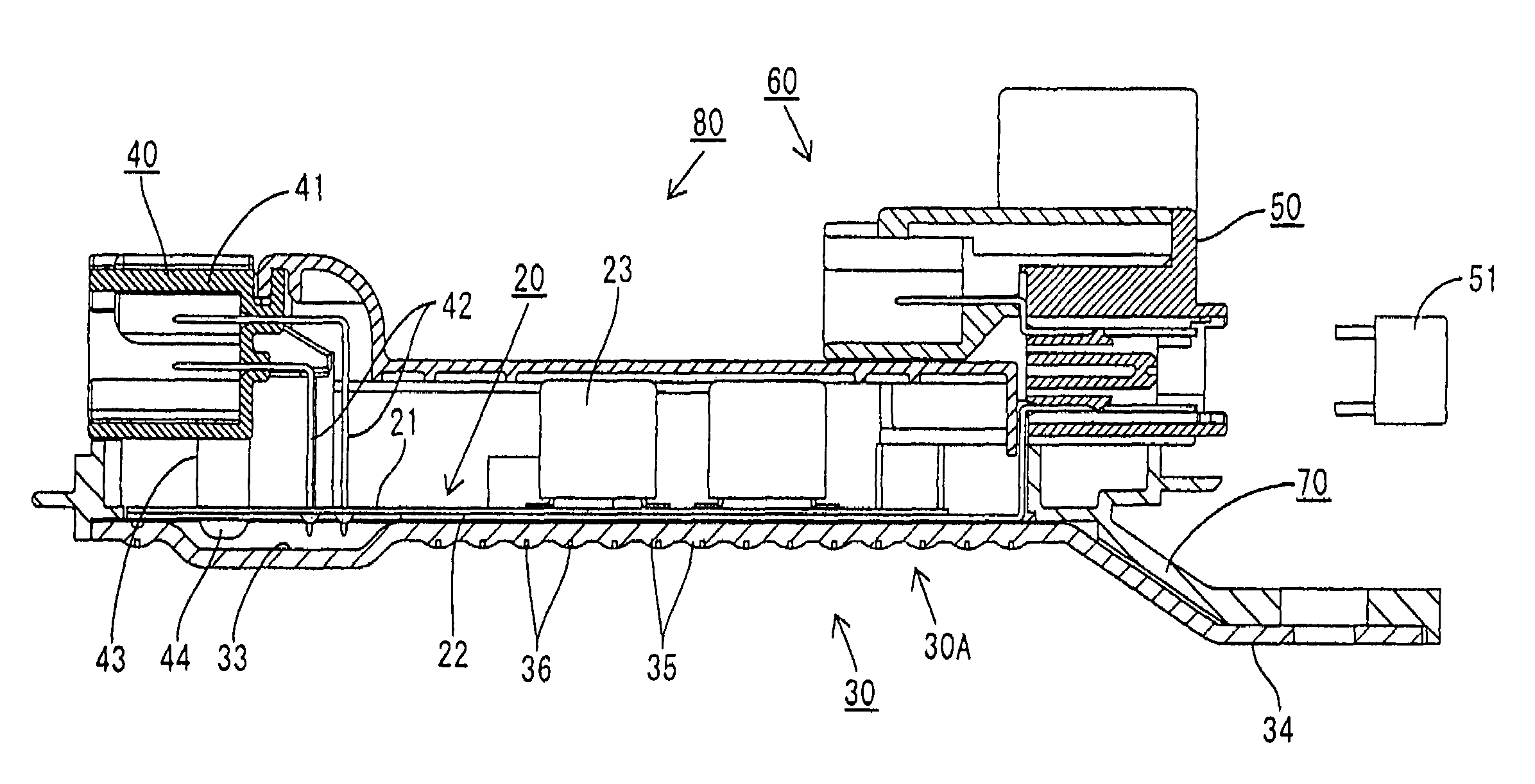
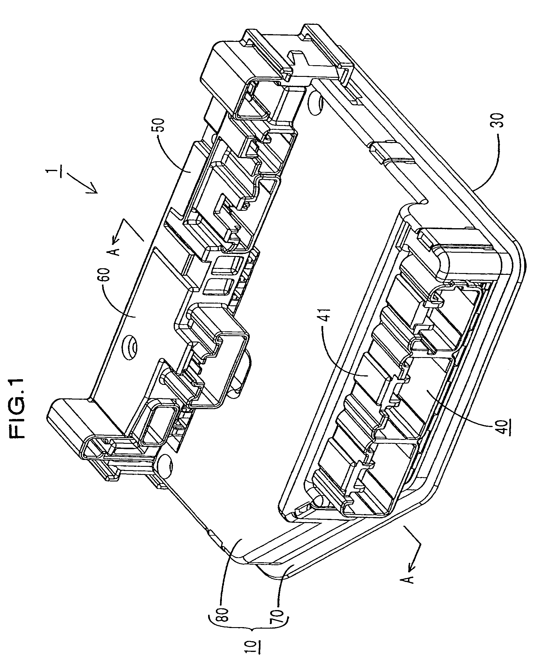
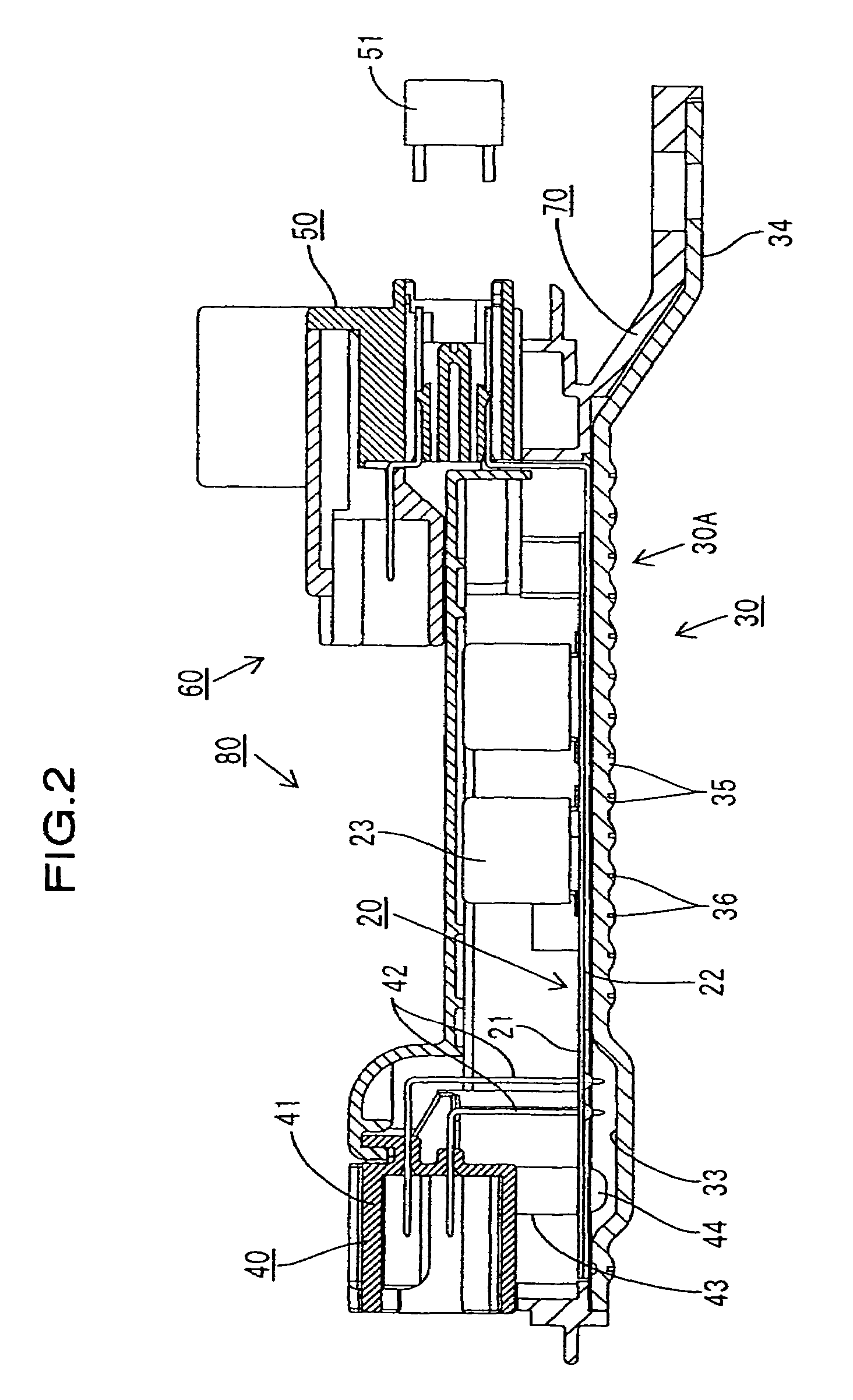
[0023]The following describes a first embodiment of the present invention with reference to FIGS. 1 to 4. FIG. 1 is a perspective view of an electric junction box according to the first embodiment; FIG. 2 is a cross-sectional view along section A-A of FIG. 1; and FIG. 3 is a partial cross-sectional front view of FIG. 1. In the...


PUM


Abstract

A heat sink in an electric junction box has thermal diffusion portions having one of convex and concave shapes on the surface. The structure enlarges a surface area of the heat sink compared to a configuration in which a surface has no concavity or convexity, thereby allowing fast heat dissipation from the surface of the heat sink to the exterior of the junction box. Further, the heat sink has the thermal diffusion portions on the entire plate surface. The structure enlarges the surface area of the heat sink compared to a configuration in which the thermal diffusion portions are provided to only a portion of the surface, thereby further enhancing the heat dissipation.

Description

CROSS-REFERENCE TO RELATED APPLICATIONS[0001]The present disclosure relates to subject matter contained in priority Japanese Application No. 2004-277038, filed on Sep. 24, 2004, which is herein expressly incorporated by reference in its entirety.BACKGROUND OF THE INVENTION[0002]1. Field of the Invention[0003]The present invention relates to an electric junction box and more particularly to an electric junction box including a heat sink including one of convex and concave shapes on the surface thereof.[0004]2. Description of Related Art[0005]The prior art, such as Japanese Patent Laid-open Publication No. 2003-164039, discloses an electric junction box that distributes power from a common vehicle power source to electronic units. In the electric junction box of the prior art, a bus bar board that constitutes a power circuit is adhered to a lower surface of a control circuit board. The bus bar board is provided with a heat sink material on a lower surface (a surface opposite to the su...

Claims


Application Information

Patent Timeline
Patent Type & Authority Patents(United States)
IPC IPC(8): H05K7/20F28D15/00
CPCB60R16/0239H05K7/026H05K7/20854
Inventor KITA, YUKINORI
Owner SUMITOMO WIRING SYST LTD
Why Eureka
Try Eureka