LED illuminating device and light engine thereof

a technology of led illuminating devices and light engines, which is applied in the direction of semiconductor devices for light sources, indirect heat exchangers, lighting and heating apparatus, etc., can solve the problems that the heat dissipation device, such as the heat sink or the combination of heat sink and cooling fan, cannot meet the requirements of heat dissipation

Inactive Publication Date: 2009-09-24
HON HAI PRECISION IND CO LTD
View PDF8 Cites 20 Cited by
  • Summary
  • Abstract
  • Description
  • Claims
  • Application Information

AI Technical Summary

Problems solved by technology

Therefore, heat dissipation of the LED illuminating device is a problem inhibiting the application of the LED illuminating device, which requires to be resolved.
Otherwise, the brightness, lifespan, and reliability of the LED illuminating device will be seriously affected.
Conventional heat dissipation devices, such as heat sinks or a combination of heat sink and cooling fan, can no longer satisfy the heat dissipation requirement of the high brightness LED illuminating device.

Method used


Image

  • LED illuminating device and light engine thereof
  • LED illuminating device and light engine thereof
  • LED illuminating device and light engine thereof

Examples


Embodiment Construction

[0017]Reference will now be made to the drawing figures to describe the various embodiments in detail.

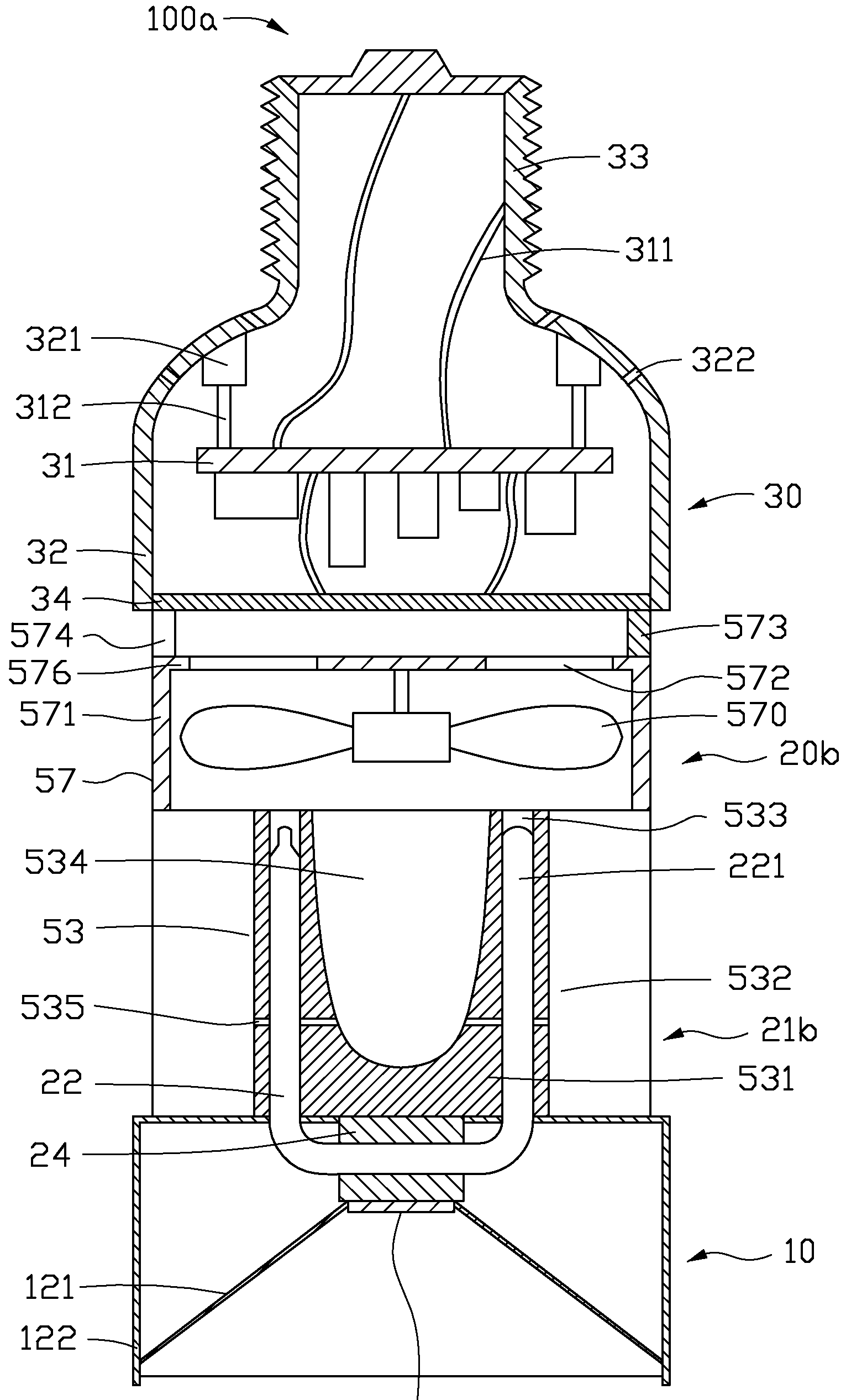
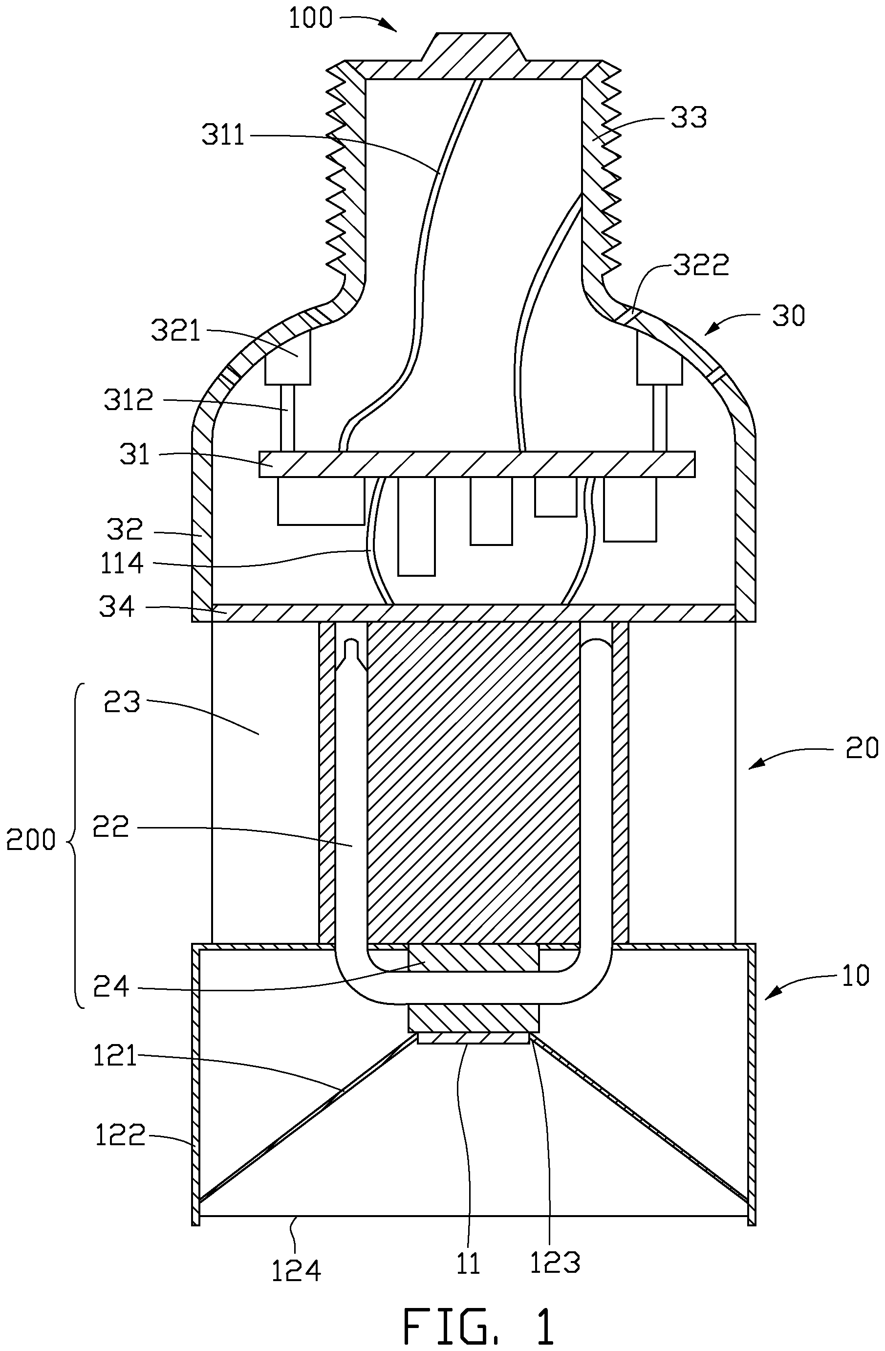
[0018]FIG. 1 is a cross-sectional view of an LED illuminating device 100 in accordance with an embodiment of the present invention. The LED illuminating device 100 includes an optical section 10, an electrical section 30, and a heat dissipation section 20 arranged between the optical section 10 and the electrical section 30. The LED illuminating device 100 is substantially cylindrical. The optical section 10 is disposed at a front end of the LED illuminating device 100, while the electrical section 30 is disposed at a rear end of the LED illuminating device 100.

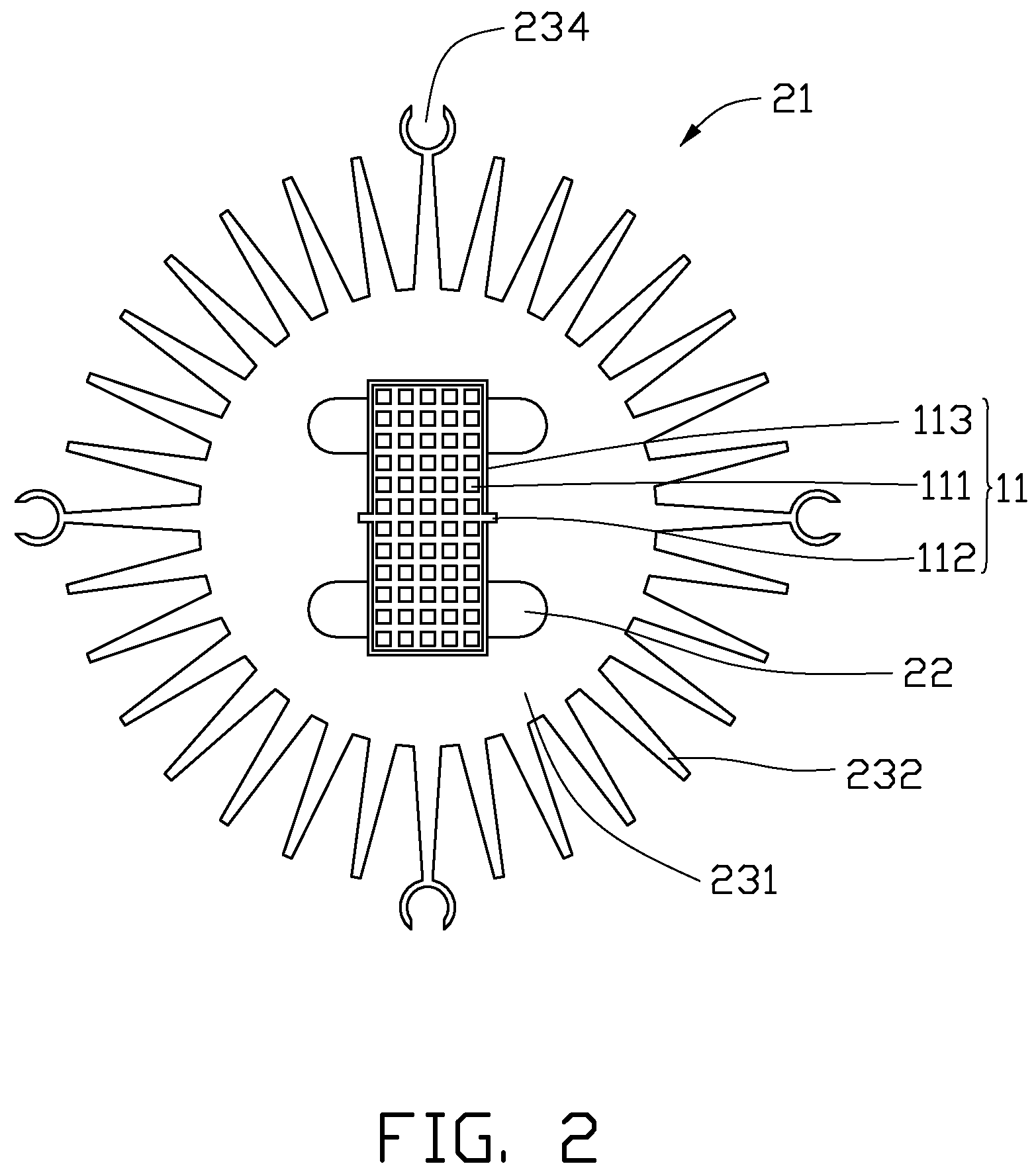
[0019]The optical section 10 includes a housing 122, a light reflector 121, a light source 11, and an optical lens 124. A rear end of the housing 122 is coupled to the heat dissipation section 20, and a front end of the housing 122 is provided with the optical lens 124. The light reflector 121 and the light source 11 are rece...


PUM


Abstract

An LED illuminating device includes an optical section (10), an electrical section (30), and a heat dissipation section (20) arranged between the optical section (10) and the electrical section (30). The heat dissipation section is provided with a heat dissipation device (200) which includes a heat sink (23), a mounting seat (24), and a heat pipe (22) connecting the mounting seat with the heat sink. The heat sink includes a solid base (231) and a plurality of fins (232) extending radially and outwardly from the base. The base is provided with a through hole (233). Alight source (11) is provided in the optical section and attached to the mounting seat. The heat pipe includes an evaporating portion (222) attached to the mounting seat, and a condensing portion (221) fittingly received in the through hole of the base.

Description

BACKGROUND [0001]1. Technical Field[0002]Embodiments of the present invention generally relates to light emitting diode (LED) illuminating devices, and particularly to an LED illuminating device with a high heat dissipating efficiency and a light engine of the LED illuminating device.[0003]2. Description of Related Art[0004]Presently, LEDs (light emitting diodes) are preferred for use in LED illuminating devices rather than CCFLs (cold cathode fluorescent lamps) due to a high brightness, a long lifespan, and a wide color range of the LED.[0005]For an LED, eighty percents to ninety percents of the power consumed by the LED is converted into thermal energy, and only ten percents to twenty percents of the power consumed by the LED is converted into light. In addition, a plurality of LEDs are generally packaged in a single LED illuminating device in order to obtain a desirable illumination brightness. Therefore, heat dissipation of the LED illuminating device is a problem inhibiting the...

Claims


Application Information

Patent Timeline
Patent Type & Authority Applications(United States)
IPC IPC(8): F21V29/02
CPCF21V29/004F21V29/89F21Y2101/02F28D15/0266F28F1/12F21V29/006Y10S362/80F28D15/0275F21K9/137H01L2924/0002F21V29/02F21V29/83F21V29/677F21V29/75F21V29/773H01L2924/00F21K9/233F21Y2115/10F21V29/51F21V29/67
Inventor LIU, TAY-JIAN
Owner HON HAI PRECISION IND CO LTD
Why Eureka
Try Eureka