

Apparatus and method for enhanced heat transfer
a technology of enhanced heat transfer and apparatus, applied in the field of thermal management technology, can solve the problem that the vibration device described below exceeds the performance of conventional immersion cooling devices, and achieve the effect of dissipating more energy
- Summary
- Abstract
- Description
- Claims
- Application Information
AI Technical Summary
Benefits of technology
Problems solved by technology
Method used
Image

Examples
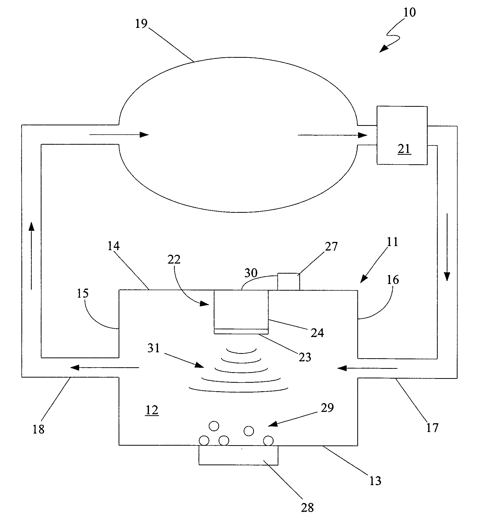
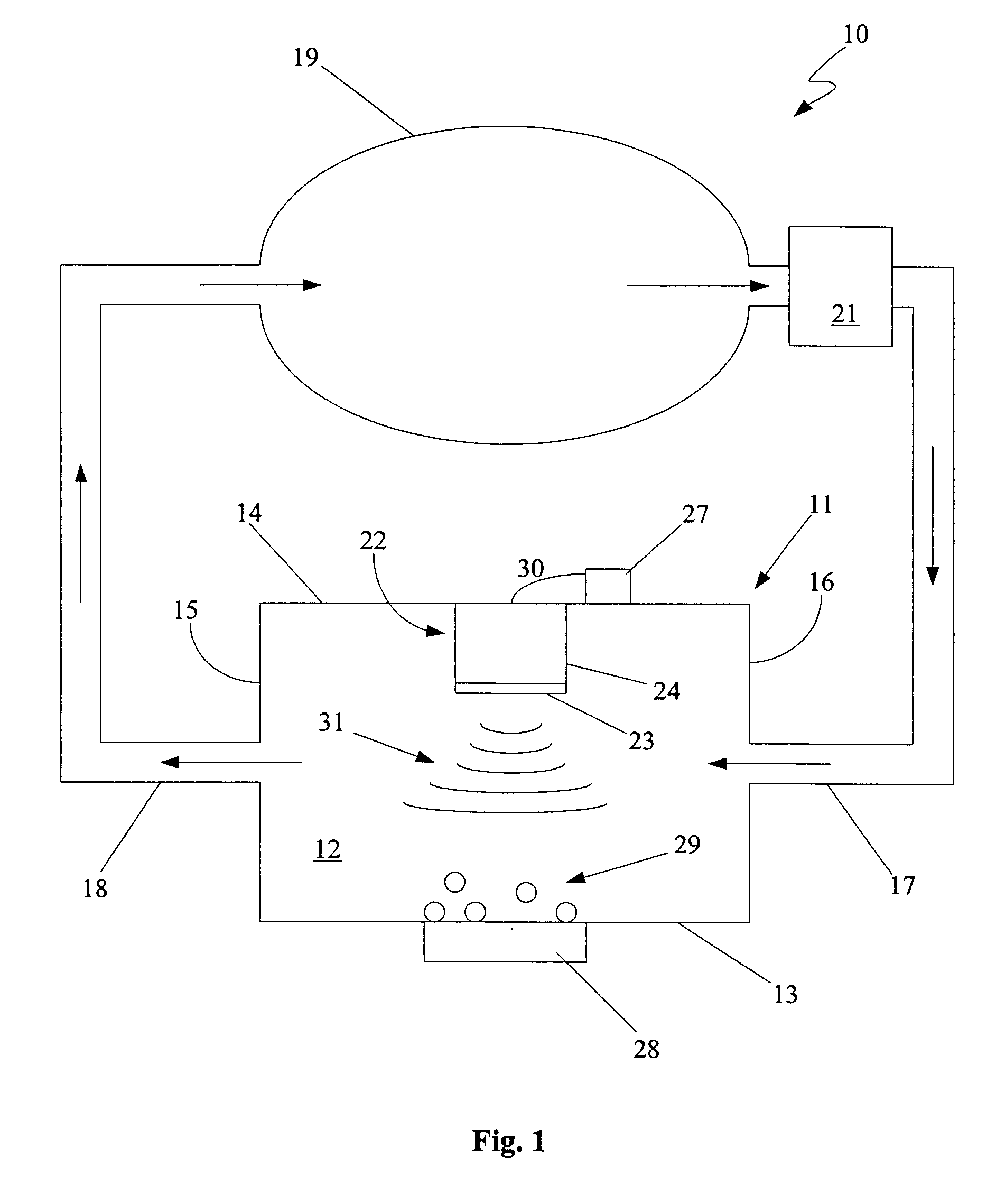
embodiment 10
[0025] The chamber 11 could be constructed of any suitable material. Generally, the material used for the chamber 11 will depend to some degree on the particular fluid 12 in the chamber 11 and on the particular heat transfer characteristics desired. The preferred material from which the chamber 11 is to be constructed is a light-weight metallic material from which the chamber 11 can be easily and inexpensively manufactured. For example, the material for the chamber 11 of the present embodiment 10 is aluminum.
[0026] In the present embodiment 10, the entire chamber 11 is constructed from an aluminum material. However, in an alternative embodiment, the chamber 11 is manufactured from more than one material. In other words, different parts of the chamber 11 are manufactured from different materials. Such a configuration minimizes heat transfer to certain parts of the chamber 11, while maximizing heat transfer to other parts of the chamber 11.
[0027] More specifically, in this alternativ...
embodiment 50
[0056] An alternative embodiment of a VIBE apparatus 60 is depicted in FIG. 6. This embodiment 60 is very similar to the previous embodiment 50. However, small synthetic jet actuators 61, 62 have been placed within the chamber 11. Synthetic jet actuators, generally, are described in detail in U.S. Pat. No. 5,758,853 to Glezer et al., entitled “Synthetic Jet Actuators and Applications Thereof,” which is incorporated herein by reference. Basically, the synthetic jet actuators 61, 62 create jets 63, 64 of fluid without net mass injection into the chamber 11. The fluidic jets 63, 64 agitate the fluid 12 in the chamber 11 resulting in more effective heat transfer.
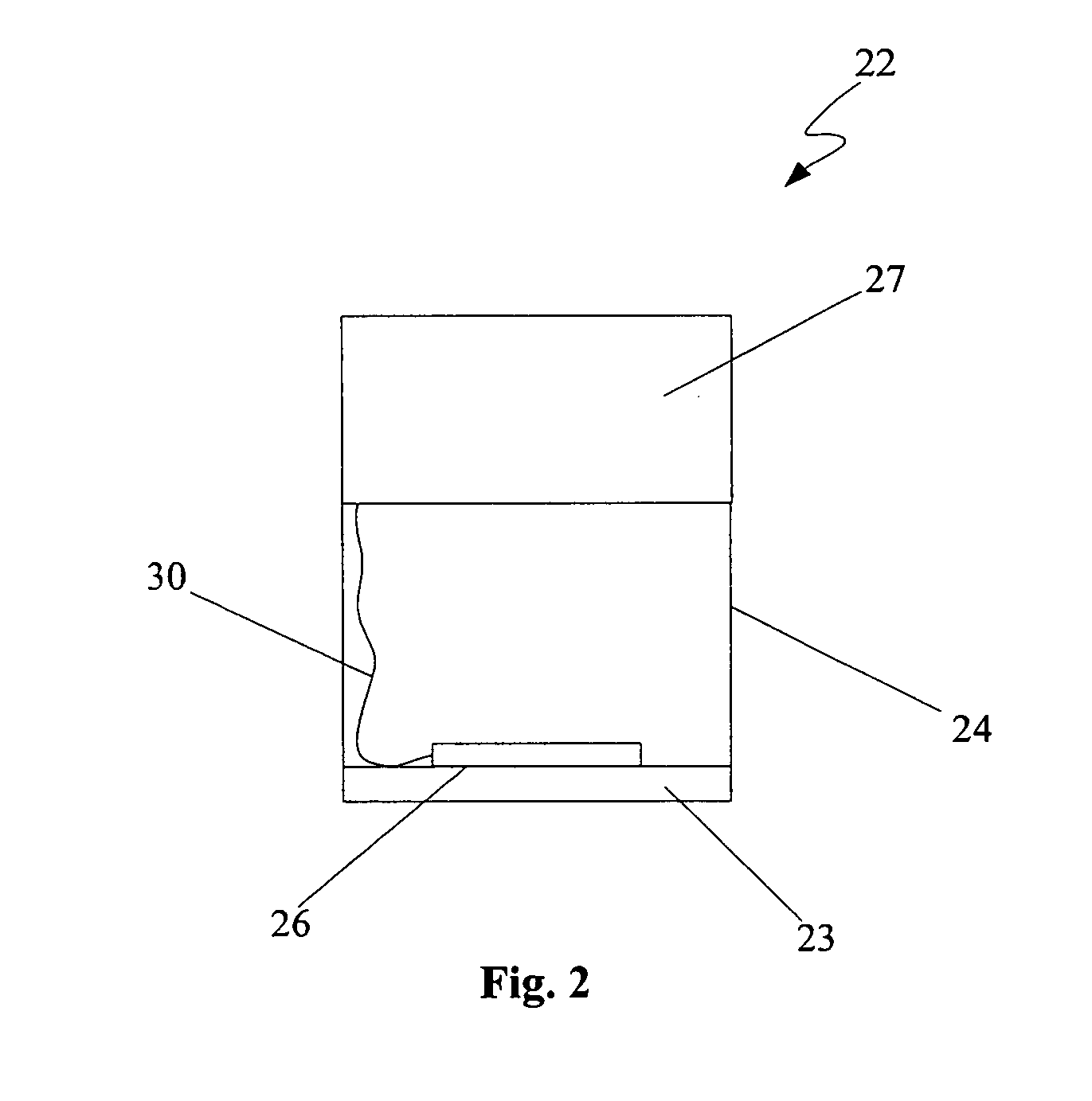
[0057] Other alternative embodiments of the VIBE device involve modifications of the actuator 22. One of these alternative embodiments involves using more than one actuator 22 in the chamber 1. An array of actuators is positioned along the upper wall 14 of the chamber 11. In another alternative embodiment, the actuator 22 compri...
PUM
 Abstract
Description
Claims
Application Information