Off-set clamp mechanism and associated method for minimally invasive surgery

Inactive Publication Date: 2002-12-17
GRANIT MEDICAL INNOVATION +1
View PDF38 Cites 227 Cited by
  • Summary
  • Abstract
  • Description
  • Claims
  • Application Information

AI Technical Summary

Benefits of technology

The control wheel is provided on an upper surface with two camming devices, which alternatively engage a wedge or tooth mounted on an under surface of the upper jaw. In a locking position of the wheel, a V-shaped guide receives the tooth and aligns the jaws to force an engagement of self-locking elements on a mounted surgical fastener upon closing of the jaws. In a skewing position of the wheel, a second wedge deflects the wedge or tooth on the upper jaw, causing a skewing motion of the jaws and preventing an

Problems solved by technology

However, by the very positive locking feature, i.e., by virtue of having a locking mechanism which permanently h

Method used


Image

  • Off-set clamp mechanism and associated method for minimally invasive surgery
  • Off-set clamp mechanism and associated method for minimally invasive surgery

Examples


first embodiment

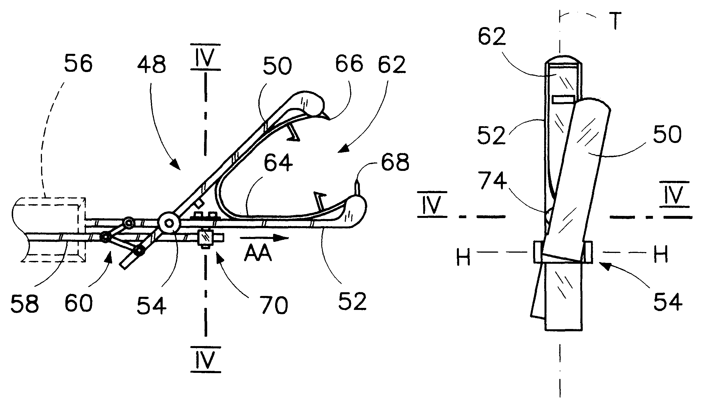
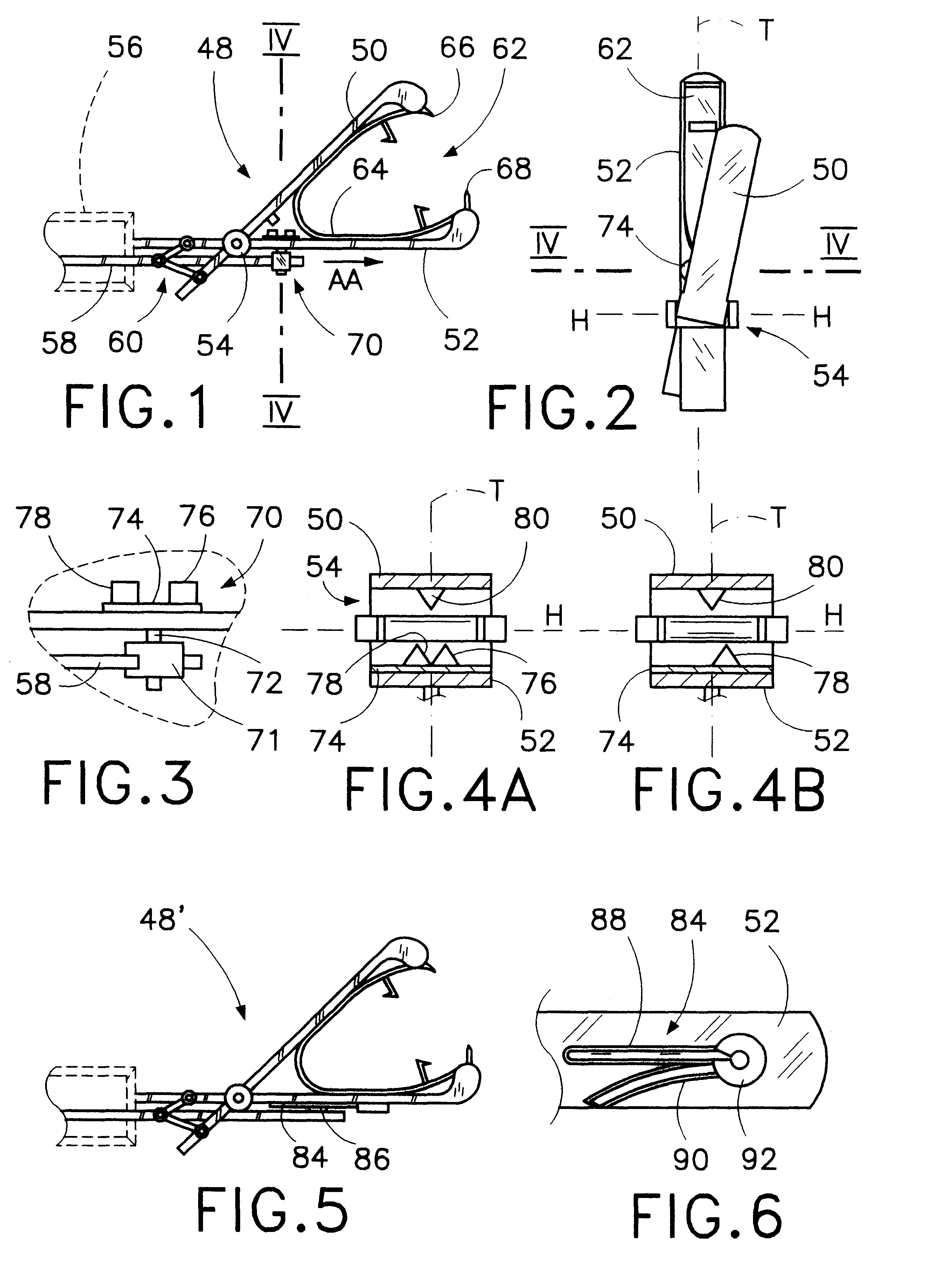
an instrument for setting a self-locking surgical clamp or fastener, as shown in FIG. 1, includes a clamping mechanism 48 at a distal end thereof (not designated), comprising an upper jaw 50 and a lower jaw 52 joined at a hinge or pivot point 54. The lower jaw is joined to a rigid elongate sheath 56 which in turn substantially houses a drive rod 58. Drive rod 58 actuates an opening and closing motion of the jaws from a proximal end (not shown) of the instrument. A linkage 60 joins the drive rod to jaws 50, 52 on a proximal side of hinge 54, and is designed to urge the jaws into a open configuration when rod 58 is pushed in a distal direction AA, or alternatively draw the jaws into a closed configuration when the rod is withdrawn in a proximal direction opposite to direction AA, as indicated in FIG. 1.

Hinge 54 is designed with mechanical tolerances in order to permit a full range of rotation of the jaws about a hinge or primary axis H (FIG. 2), and a limited degree of secondary rotat...

second embodiment

A second embodiment of an instrument for setting a self-locking surgical clamp or fastener is shown in FIGS. 5 and 6. Clamping mechanism 48' is structurally similar to mechanism 48, with an elimination of ratcheting device 71, shaft 72, camming wheel 74 and tooth 80. Instead, a camming effect is achieved by a camming track 84, which engages a vertical pin or projection 86 mounted on drive rod 58. Camming track 84 is in turn comprised of a straight branch 88 and a curved branch 90, which branches meet in a ratcheting device 92. Ratcheting device 92 redirects pin 86 alternatively down the straight branch 88 and down the curved branch 90 upon each distally extreme movement of the pin, in a filly opened configuration of the jaws. Upon an engagement of curved branch 90, a resulting deflection of drive rod 58 is communicated to a proximal end 94 of the upper jaw through a modified linkage 60'. Linkage 60' enjoys an enhanced degree of mechanical tolerance relative to linkage 60, allowing a...


PUM


Abstract

A surgical clamping device comprises a first jaw and a second jaw, with a self-locking surgical fastener mountable thereon. The jaws have at least a first closing configuration and a second closing configuration, the first closing configuration designed to reduce a lateral dimension of a clamping device with mounted fastener, without thereby engaging locking devices on the selflocking surgical fastener, the second closing configuration designed to cause an engagement of the self-locking devices, thereby allowing a demounting of the fastener and a permanent disposition thereof in tissue. In a first closing configuration an approximation of the jaws in a transverse plane thereof is accompanied by an out-of-plane movement, comprising translation, or rotation about an axis in the plane, the rotation in turn comprising twisting-rotation about an axis essentially parallel to a longitudinal axis of the jaws, or skewing-rotation about an axis essentially perpendicular to a longitudinal axis of the jaws. An alternative engagement of the first closing configuration and the second closing configuration is effected by a ratcheting device in conjunction with a camming device, or any means of actuation known in the mechanical arts.

Description

This invention relates to the field of surgeries conducted through a tubular guide or cannula, including but not limited to arthroscopic, endoscopic, laparoscopic, thoracoscopic, and intravascular surgeries. In particular, this invention relates to instruments insertable through a cannula and carrying a surgical fastener to a distal end thereof. This invention also relates to a method for clamping organic tissues.Various minimally invasive surgical techniques have been developed involving the passage of instruments down a tubular guide or cannula inserted into an existing orifice or duct of the human body, penetrating a bodily wall, or both. These techniques include, but are not limited to, arthroscopic, endoscopic, laparoscopic, thoracoscopic, and intravascular surgeries, although in laparoscopic surgery the tubular penetration may be limited to the bore of a trocar sleeve, an extended cannula being omitted. In these techniques, space, and in particular space perpendicular to a lon...

Claims


Application Information

Patent Timeline
IPC IPC(8): A61B17/122A61B17/12A61B17/28A61B17/128
CPCA61B17/122A61B17/1285A61B2017/00738A61B2017/2939
Inventor WILK, PETER J.WHITNEY, JAMES R.
Owner GRANIT MEDICAL INNOVATION
Why Eureka
Try Eureka