Structural truss system with adjustable mechanical mounting track and internal conduit accessible from removable sidewall

a technology of structural trusses and mechanical mounting tracks, which is applied in the direction of direction finders using ultrasonic/sonic/infrasonic waves, coupling device connections, instruments, etc., can solve the problems of constant damage to wiring being mounted on the outside of the support structure, constant risk of damage from abrasion, and problems in the mounting of heavy lighting and sound equipmen

Inactive Publication Date: 2002-12-24
KIRKPATRICK BRUCK +1
View PDF6 Cites 34 Cited by
  • Summary
  • Abstract
  • Description
  • Claims
  • Application Information

AI Technical Summary

Problems solved by technology

A number of problems arise in this mode of construction and wiring for the heavy devices such as spotlights and speakers used on a modern stage.
First, the wiring being mounted on the outside of the support structure is subject to constant damage from abrasion from heavy poles adjacent to the support beam.
Further, on stages designed for rapid deployment in venues in different cities, the constant removal and reinstallation of the wires in this manner subjects them to constant risk of damage from abrasion and impact during construction and removal of the stage structure.
Further, problems arise in the mounting of the heavy lighting and sound equipment from the support beams.
If the clamp loosens from vibration the light or speaker or other device will become disoriented from its intended direction.
Also, the very nature of the intense compression needed to insure a firm mount to the support beam exterior also insures a hard time uninstalling the component due to the force needed to decompress the fitting on the structure.
Such a compression mounting also causes delays in the installation of the equipment on new venues due to the time involved in mechanically turning the compression screws or other devic...

Method used


Image

  • Structural truss system with adjustable mechanical mounting track and internal conduit accessible from removable sidewall
  • Structural truss system with adjustable mechanical mounting track and internal conduit accessible from removable sidewall
  • Structural truss system with adjustable mechanical mounting track and internal conduit accessible from removable sidewall

Examples


Embodiment Construction

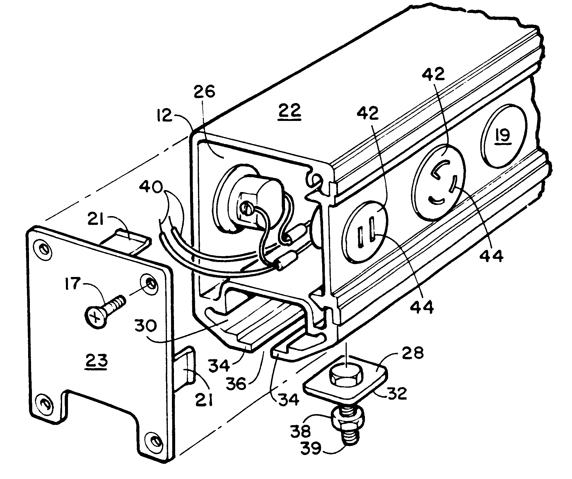
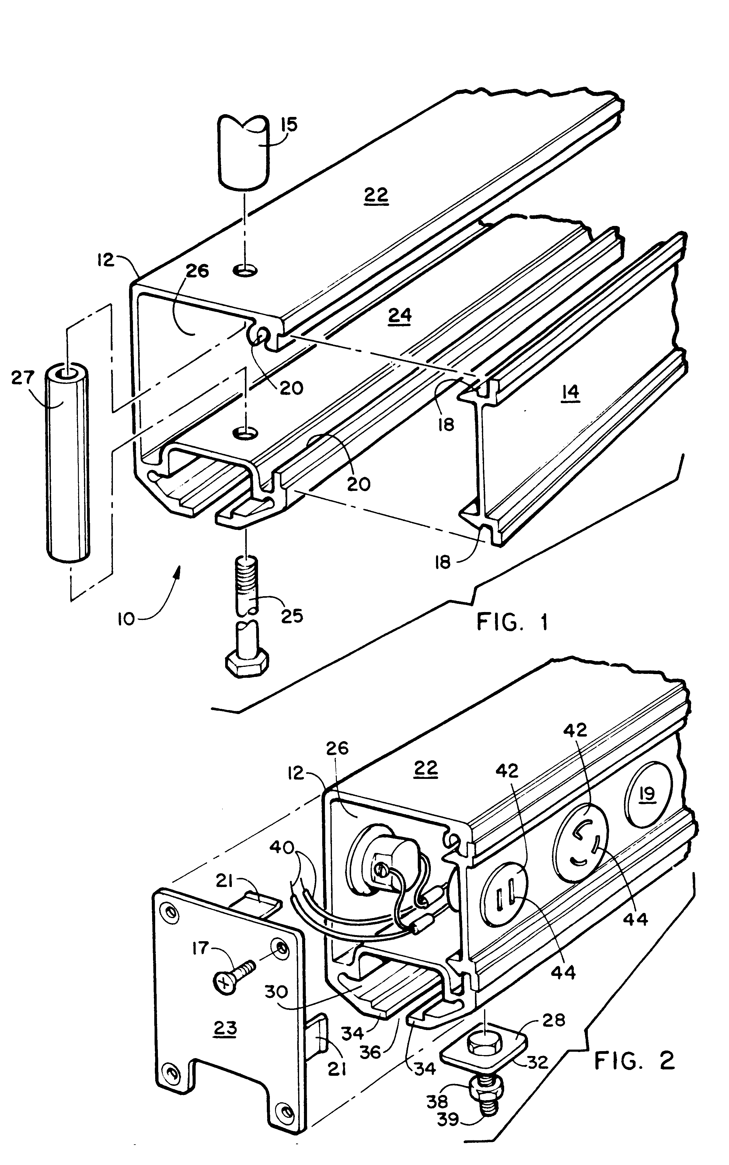
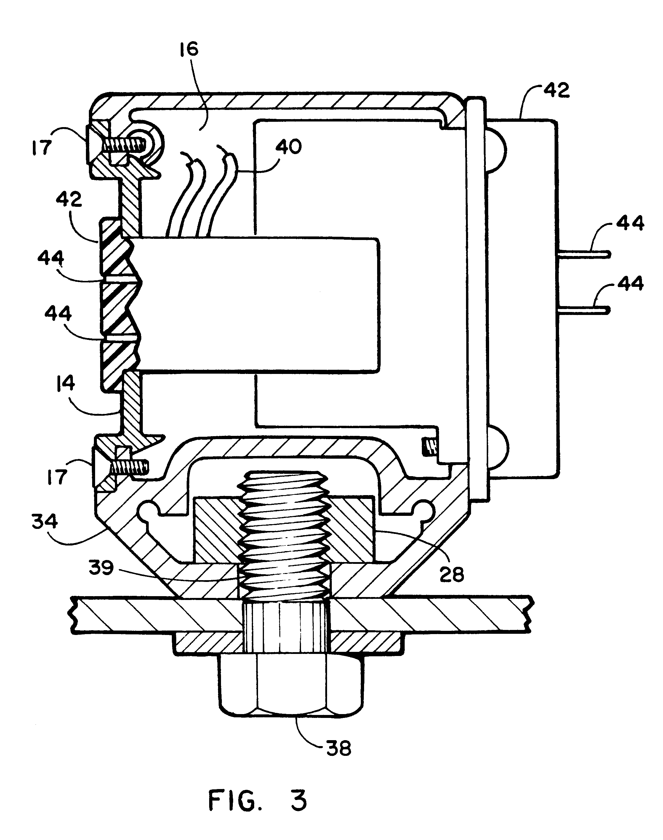
Referring now to the drawing Figures, specifically FIGS. 1 through 3 depict preferred embodiments of the device herein disclosed with the various components thereof in operative positions. FIG. 1 depicts the device 10 in a perspective end view of the support beam 12 showing the removably mountable sidewall 14 dismounted from the support beam 12. This removable mounting ability provides the user with the ability to remove the sidewall 14 to place, remove, or otherwise service wiring that may be carried in the conduit 16 formed on the interior of the support beam 12.

The sidewall 14 is secured by a means of cooperative engagement of the sidewall 14 to the support beam 12 which in this case is shoulders 18 which cooperatively engage slots 20 formed into the support beam 12. The shoulders 18 run the entire length of the sidewall 14 and cooperatively engage the slots 20 which are operatively placed along the support beam 12 parallel to the center axis of the support beam 12. Optionally, s...


PUM


Abstract

A structural truss system and electrical conduit for suspended mounting of electrical components such as stage lighting and remote controlled equipment featuring an elongated support beam with removable endcaps and a sidewall. The sidewall is cooperatively engageable with the support beam along substantially its engire length and allows access to the conduit formed inside when engaged with the support beam. A mounting track formed on the exterior surface of said bottom wall of the support beam and provides a slidably engageable mount for component mounts that attach to electrical components such as lights thereby providing positioning ability for the attached components. One or a plurality of electrical plugs or similiar attachments communicate through the sidewalls with wires running in the conduit and allow the electrical components to be properly situated in the mounting track and then plugged into the electrical power or control signals provided by the internal wiring.

Description

1. Field of the InventionThe present invention relates to support members used for attachment of lighting and electrical components. More particularly it relates to a structural truss device for use in construction of theatrical lighting and mounting of electrical components such as spotlights, and speakers, over stages used by entertainers. The device provides a combination of an enclosed conduit for routing electrical wires and control wires protected from external harm while inside the interior cavity. The device further provides a track for the adjustable mounting of lights and other heavy stage electrical equipment therefrom along with and a removable sidewall which provides access to the wires communicating through the enclosed conduit. Optional compression bolts may be used to increase compaction on the sidewall in its mountings and to also allow for mounting to support structures or wires if desired.2. Prior ArtModern stage productions frequently involve the necessity of ove...

Claims


Application Information

Patent Timeline
IPC IPC(8): H01R25/00H01R13/73H01R25/16H01R27/00
CPCH01R13/73H01R25/16H01R27/00
Inventor WILSON, STEVEN W.
Owner KIRKPATRICK BRUCK
Why Eureka
Try Eureka