
Automatic stage lighting tracking system based on thermal imaging

A stage lighting and automatic tracking technology, applied in the control/adjustment system, TV system components, optics, etc., can solve the problems of low degree of automation, poor flexibility, time-consuming and laborious, and achieve good use effect and design. Reasonable and simple structure

Inactive Publication Date: 2014-06-04
XIAN JINHE OPTICAL TECH
View PDF0 Cites 16 Cited by
  • Summary
  • Abstract
  • Description
  • Claims
  • Application Information

AI Technical Summary

Problems solved by technology

[0002] When an actor performs on the stage, in order to let the audience see more clearly, it is often necessary to use a high-brightness aperture to illuminate, but when the actor walks, it is necessary to manually control the rotation of the light so that the light can track the performer. The existing control light The tracking methods mainly include: (1) manual control, which requires the operator to operate the lighting equipment at a higher place, which is laborious and laborious, and the effect is not good; (2) through the remote control device, the computer system is used to implement online operation, which requires professional It is inconvenient for the monitoring personnel to operate, and the degree of automation is not high; (3) It is a program to program the rotation angle of the lighting equipment through a pre-designed itinerary, and its flexibility is not good, and the on-site actors cannot freely change the route
Existing methods have certain defects, and cannot meet the requirements of accurate tracking of lights to achieve increasing stage effects.

Method used


Image

  • Automatic stage lighting tracking system based on thermal imaging

Examples


Embodiment Construction

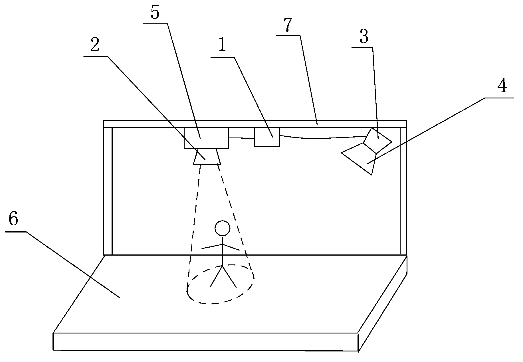
[0016] Such as figure 1 As shown, the present invention includes a stage light 2, a cloud platform 5, a control module 1, an infrared camera 4 and an image processing module 3, and the stage light 2 is installed on the stage roof 7 above the stage 6 through the platform 5. The stage light 2 is installed on the stage roof 7, the stage light 2 is installed on the cloud platform 5 and driven to rotate by the platform 5, the control module 1 is installed on the stage roof 7, the control module 1 and the platform 5 Connected and used to control the motor rotation of the cloud platform 5, the operating wavelength of the infrared camera 4 is 4-20 microns, the infrared camera 4 is arranged on the stage roof 7 and is used to shoot the target image on the stage 6, so The infrared camera 4 is connected with the image processing module 3 and is used to transfer the target image taken by the infrared camera 4 to the image processing module 3 for storage and processing by the image processi...


PUM


Abstract

The invention discloses an automatic stage lighting tracking system based on thermal imaging. The automatic stage lighting tracking system comprises a stage lamp, a holder, a control module, an infrared camera and an image processing module. The stage lamp is installed on a stage roof above a stage through the holder. The control module is installed on the stage roof. The control module is connected with the holder and is used for controlling rotation of a motor of the holder. The infrared camera is arranged on the stage roof and is used for shooting a target image on the stage. The infrared camera is connected with the image processing module and is used for transmitting the target image shot by the infrared camera to the image processing module for storing and processing. The image processing module is arranged on the stage roof. The image processing module is connected with the control module and transmits a result processed by the image processing module to the control module. According to the automatic stage lighting tracking system, the infrared camera acquires the target image needing to be tracked, and then the stage lamp locks the image to achieve the purpose of automatic target tracking.

Description

technical field [0001] The invention relates to a stage lighting control system, in particular to an automatic tracking system for stage lighting based on thermal imaging. Background technique [0002] When an actor is performing on the stage, in order to make the audience see more clearly, it is often necessary to illuminate with a high-brightness aperture, but when the actor walks around, it is necessary to manually control the rotation of the light so that the light can track the performer. The existing control light The tracking methods mainly include: (1) manual control, which requires the operator to operate the lighting equipment at a higher place, which is laborious and laborious, and the effect is not good; (2) through the remote control device, the computer system is used to implement online operation, which requires professional (3) It is a program for programming the rotation angle of the lighting equipment through a pre-designed itinerary, which is not flexible ...

Claims


Application Information

Patent Timeline
IPC IPC(8): G03B15/05H04N5/232G05D3/00
Inventor 杜兵
Owner XIAN JINHE OPTICAL TECH
Learn More