Optical monitoring for OXC fabric

Inactive Publication Date: 2003-01-14
LUCENT TECH INC
View PDF7 Cites 24 Cited by
  • Summary
  • Abstract
  • Description
  • Claims
  • Application Information

AI Technical Summary

Problems solved by technology

A problem with this arrangement is that the optical taps direct a portion of the optical signal away from the I/O fiber.
Accordingly, the optical taps add considerable cost to the OXC because they are required for each of the I/O fibers.
After

Method used


Image

  • Optical monitoring for OXC fabric
  • Optical monitoring for OXC fabric
  • Optical monitoring for OXC fabric

Examples


Embodiment Construction

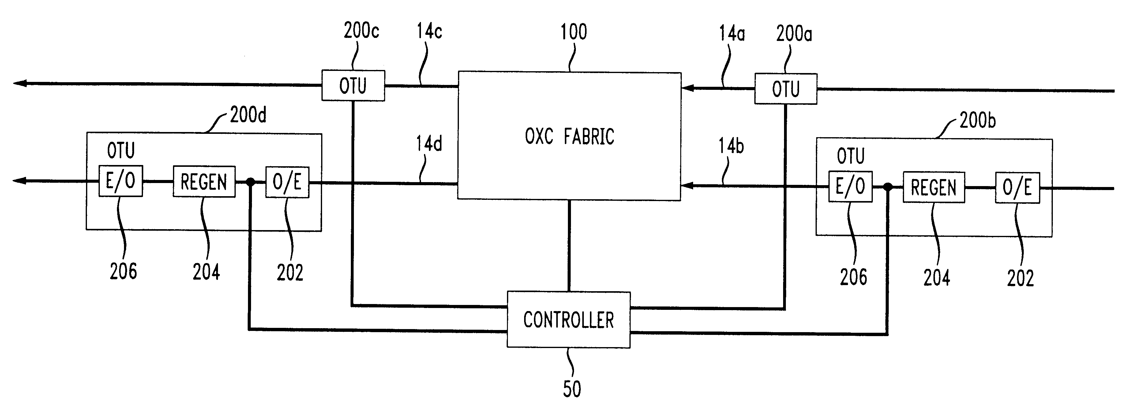
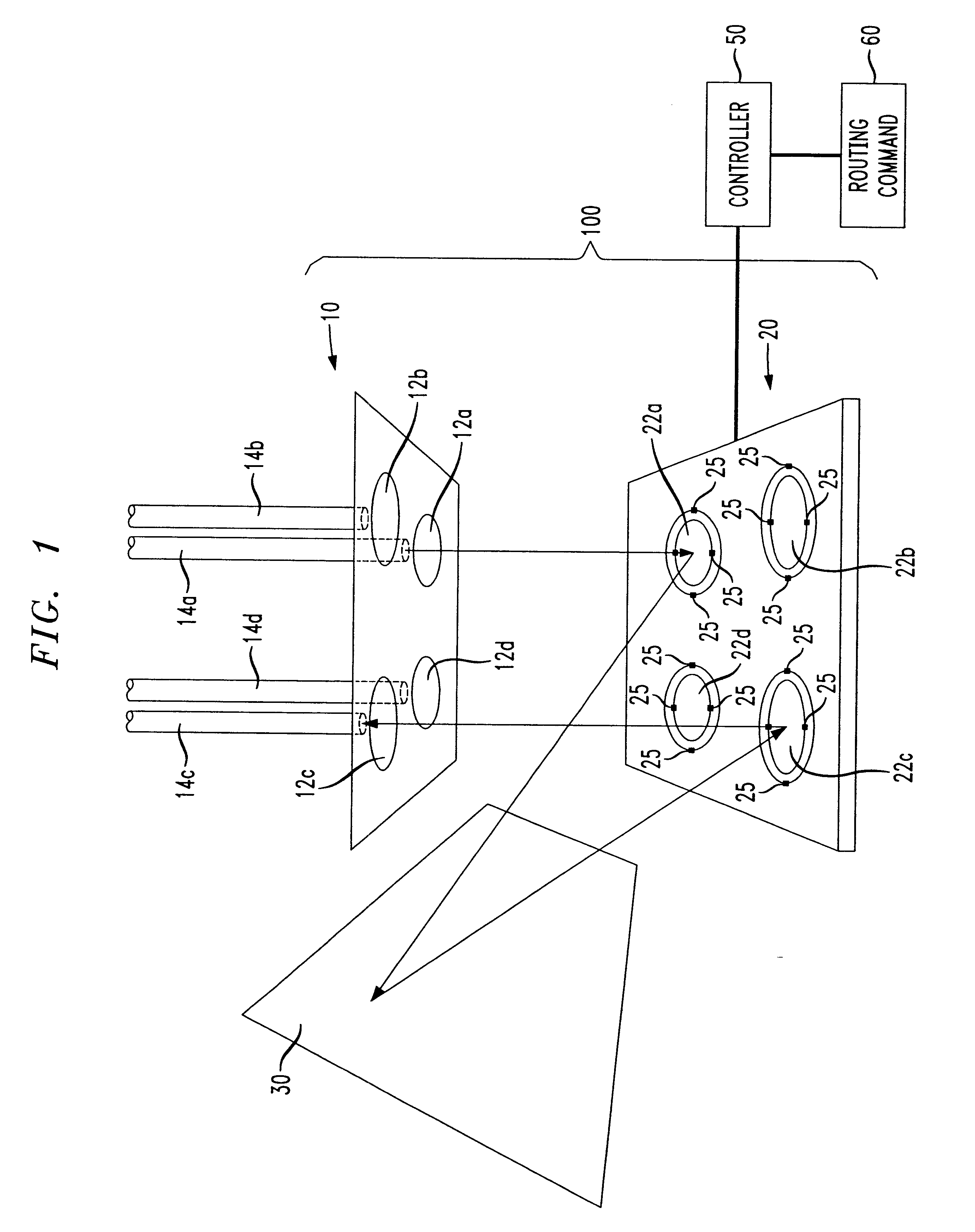
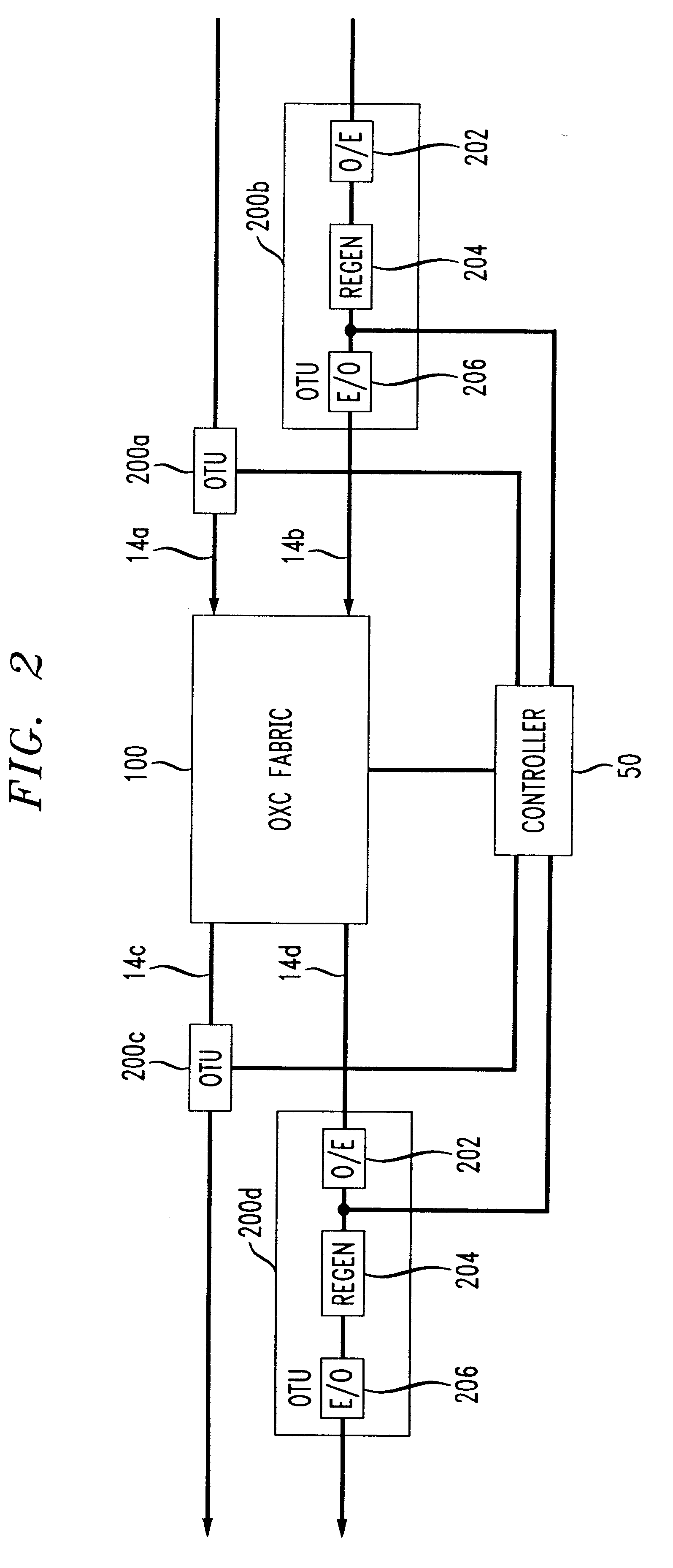
Referring to FIG. 1, an Optical Crossconnect (OXC) fabric 100 comprises an array of imaging lenses 10, a mirror array 20, and a reflector 30. The OXC 100 is typically formed using Micro Electro-Mechanical Systems (MEMS) technology. The array of imaging lenses 10 comprises lenses 12a-12d respectively aligned with I / O fibers 14a-14d. The mirror array 20 includes a plurality of mirrors 22a-22d respectively corresponding to the I / O fibers 14a-14d. The lenses 12a-12d respectively correspond to the I / O fibers 14a-14d for focussing the optical signals transmitted between the I / O fibers 14a-14d and the respective mirrors 22a-22d of the mirror array 20. To simplify the drawing and for ease of explanation of its operation, the OXC fabric 100 of FIG. 1 is shown as having four I / O fiber and mirrors. However, the OXC fabric may include any number of I / O fibers and mirrors and more typically includes a 16.times.16 array of 256 fiber and mirrors.

Each mirror 22a-22d of the mirror array 20 is connec...


PUM


Abstract

An optical crossconnect (OXC) fabric including an array of tiltable mirrors, a reflector and a plurality of optical fibers controls the position of the mirrors to optimize the transfer of a signal between an input optical fiber and an output optical fiber by monitoring the optical signal at an optical translation unit in each of the input optical fiber and the output optical fiber. The optical translation units are operable for regenerating the optical signals transmitted through the fibers.

Description

1. Field of the InventionThe present invention relates to an Optical Crossconnect (OXC) fabric for connecting an optical signal in an input fiber to an output fiber and that includes an array of I / O fibers, an array of tiltable mirrors, and a reflector.2. Description of the Related ArtAn Optical Crossconnect (OXC) device comprises an array of lenses, a corresponding array of mirrors, and a reflector. An array of I / O fibers which corresponds to the array of lenses is received in the device so that the array of mirrors corresponds to the array of I / O fibers. Each of the mirrors is tiltable about 2 axes for directing an input signal received from its corresponding I / O fiber (i.e. an input fiber) against the reflector to another mirror and to an output one of the I / O fibers, thereby signally connecting the input fiber to the output fiber and functioning as a switch.To ensure proper positioning of the mirrors for optimizing the connection of the optical signal from the input I / O fiber to...

Claims


Application Information

Patent Timeline
IPC IPC(8): H04Q11/00G02B26/08
CPCH04Q11/0005H04Q2011/0083H04Q2011/0043H04Q2011/0026
Inventor BISHOP, DAVID JOHNGILES, RANDY CLINTONNEILSON, DAVID THOMAS
Owner LUCENT TECH INC
Why Eureka
Try Eureka