Video signal coding method

a video signal and signal technology, applied in the field of video signal coding method, can solve problems such as affecting visual quality

Inactive Publication Date: 2003-01-14
LG ERICSSON
View PDF6 Cites 32 Cited by
  • Summary
  • Abstract
  • Description
  • Claims
  • Application Information

AI Technical Summary

Problems solved by technology

Accordingly, when the bitrate is controlled using the quantizer, quantization error directly affects visual quality, producing various problems.

Method used


Image

  • Video signal coding method
  • Video signal coding method
  • Video signal coding method

Examples


Embodiment Construction

Reference will now be made in detail to the preferred embodiments of the present invention, examples of which are illustrated in the accompanying drawings.

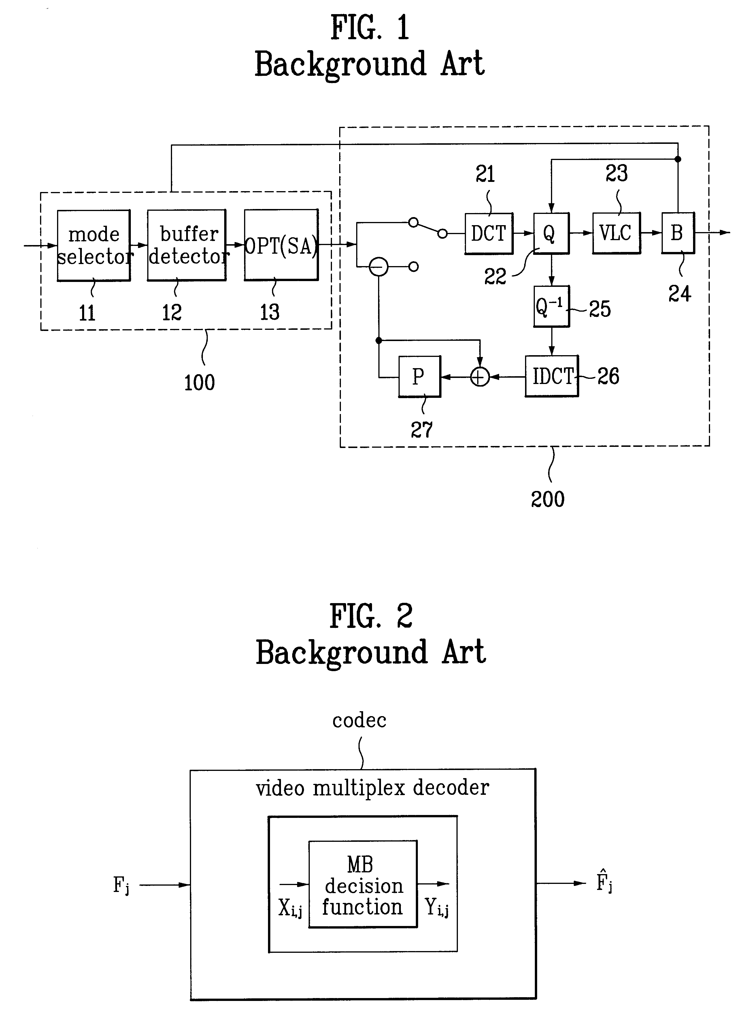
FIG. 1 is a block diagram of a conventional adaptive mode selection (AMS) video coder. Referring to FIG. 1, the AMS video coder consists of a mode controller 100 and encoder 200. Mode controller 100 includes a mode selector 11 for determining coding modes for macroblocks of input frame, a buffer 12 for storing video signals outputted from mode selector 11 to observe if overflow or underflow occurs, determining whether to skip corresponding block, and an annealing optimization module 13 for obtaining the optimal decision curve coefficient and .lambda. from the output of the buffer using a given mode. Encoder 200 includes a discrete cosine transform (DCT) module 21 for transforming a spacial domain value into a transmission domain value, a quantizer 22 for dividing the output of DCT module 21 into various levels to specify them as p...


PUM


Abstract

A video signal coding method is provided which finds proper decision curves according to characteristics of input frames and encodes the optimal macroblock by using the decision curves instead of a fixed motion / no-motion compensation curve and intra / inter coding curve. The optimal mode is selected for each macroblock of input frame and it is determined through a step of judging whether the input frame is intra mode using a given function, a step of judging whether the input frame is inter mode when it is not intra mode using a given function, a step of controlling quantizer using a predetermined critical value when it is not inter mode, and step of performing skip when the quantizer controlling step is not carried out.

Description

1. Field of the InventionThe present invention relates to a video signal coding method, and more particularly, to a video signal coding method which is able to select the optimal modes for macroblocks when a block based video signal is coded.2. Discussion of Related ArtIn transmitting of video signals outputted from a video coding application program through public switched telephone network (PST), it is preferable that a fixed bitrate is maintained for simple configuration or fixed band width of the network. Accordingly, in order to transmit the video signals in a fixed bitrate, variation in bitrate is reduced using a buffer placed between the output terminal of the encoder and channel. If the encoder controls the bitrate in transmission of video signals, the output bitrate of the encoder can be uniformly maintained to correspond to variable coding quality. However, to obtain the optimal bitrate requires simultaneous using of the two methods, that is, employing of buffer and contro...

Claims


Application Information

Patent Timeline
Patent Type & Authority Patents(United States)
IPC IPC(8): H04N7/50H04N7/46H04N7/26
CPCH04N19/176H04N19/172H04N19/149H04N19/115H04N19/61H04N19/587H04N19/117H04N19/124H04N19/132H04N19/152H04N19/192H04N19/103
Inventor RYU, CHUL
Owner LG ERICSSON
Why Eureka
Try Eureka