Computer hinge

a hinge and computer technology, applied in the field of hinges, can solve the problems that neither the recesses in the sleeves nor the grooves in the shafts can provide sufficient lubrication, and increase the manufacturing cos

Inactive Publication Date: 2003-01-21
EASTMAN KODAK CO
View PDF12 Cites 20 Cited by
  • Summary
  • Abstract
  • Description
  • Claims
  • Application Information

AI Technical Summary

Problems solved by technology

It has been found that neither the recesses in the sleeve nor the grooves in the shaft can provide sufficient lubrication for the pivotal movement between the shaft and the sleeve, especially after a long period of repeated use of the hinge.
Further, the addition of the retaining device to the hinge will increase the manufacturing cost.

Method used


Image

  • Computer hinge
  • Computer hinge
  • Computer hinge

Examples


Embodiment Construction

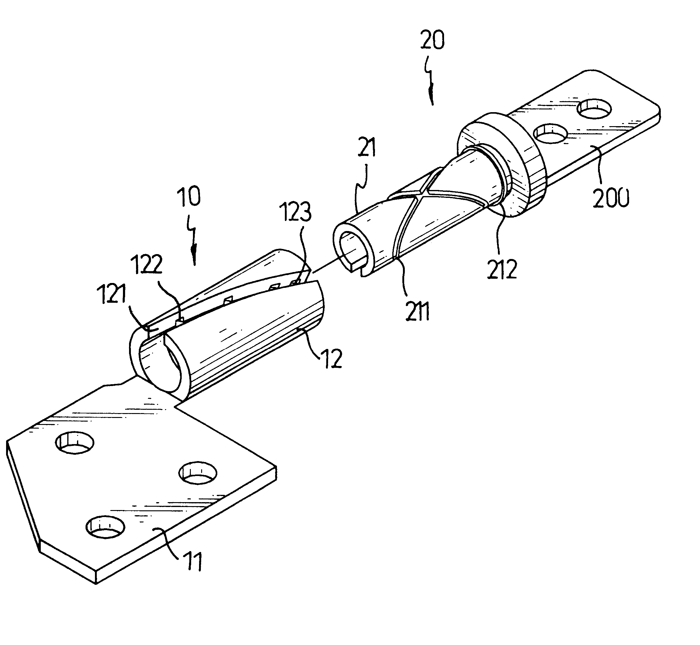
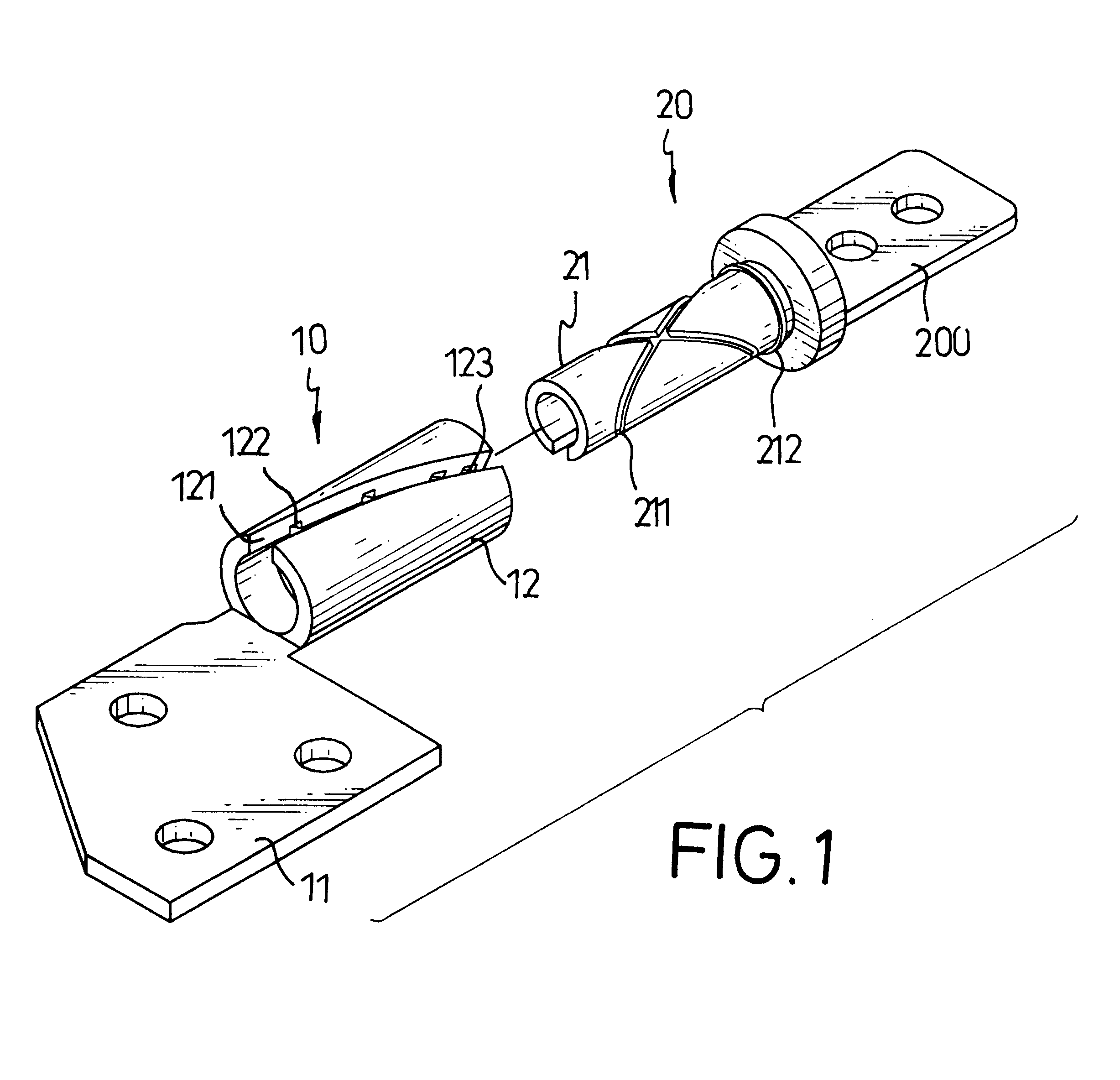
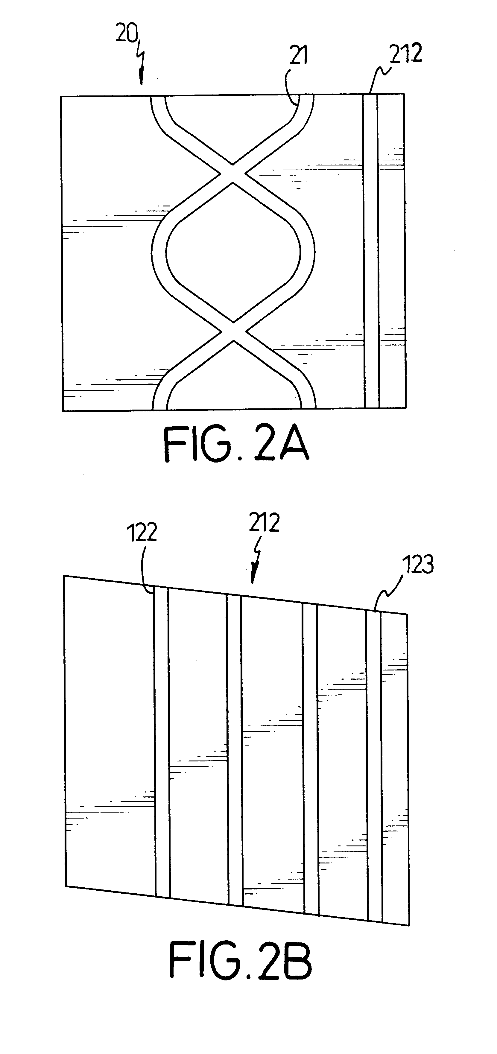
With reference to FIGS. 1, 2A, 2B, 3A and 3B, the hinge in accordance with the present invention has a sleeve (10) and a shaft (20) pivotally connected with the sleeve (10).

The sleeve (10) has a first connection plate (11) and a tubular portion (12). The first connection plate (11) is configured so that the first connection plate (11) is able to securely attach to the housing of the computer. The tubular portion (12) has an inner surface, an outer surface, a slit (121), grooves (122) and a receiving recess (123). The slit (121) is defined through the tubular portion (12). The grooves (122) and receiving recess (123) are defined in the inner surface of the tubular portion (12). Depending on the embodiment, the slit (121) is defined either longitudinal or inclined at a slight angle from longitudinal in the tubular portion (12).

The shaft (20) has a second connection plate (200), a journal (21) and a flange (212). The second connection plate (200) is configured to securely attach to the...


PUM


Abstract

A computer hinge has a sleeve and a shaft. The sleeve has a tubular portion with an inner surface, an outer surface, a slit peripherally defined through the tubular portion, grooves and a receiving recess defined in the inner surface of the tubular portion. The shaft has a journal with an outer surface integrally formed with the second connection plate and has at least one meander-line recess defined in the outer surface of the journal and a flange formed on the outer surface of the journal to correspond to the receiving recess in the tubular portion.

Description

1. Field of the InventionThe present invention relates to a hinge, and more particularly to a hinge adapted to engage respectively with the mainframe and the monitor of the computer.2. Description of Related ArtA computer hinge normally has a sleeve securely connected to the housing of the computer and a shaft securely connected to the monitor of the computer and pivotally attached to the sleeve. To enhance the pivotal movement between the sleeve and the shaft, multiple lubrication grooves or recesses are defined respectively in either the inner face of the sleeve or the shaft or the outer face of the shaft. When the lubricant is applied to the grooves or recesses and the shaft is inserted into the sleeve, the pivotal movement between the sleeve and the shaft is smoothed. Furthermore, after the shaft is inserted into the sleeve, a retaining device is necessary to secure the engagement between the shaft and the sleeve.It has been found that neither the recesses in the sleeve nor the ...

Claims


Application Information

Patent Timeline
Patent Type & Authority Patents(United States)
IPC IPC(8): E05D11/00E05D11/02G06F1/16E05D5/14E05D5/00
CPCG06F1/1681G06F1/1616E05D5/14E05D11/02E05Y2900/606Y10T16/537Y10T16/54038
Inventor LU, SHENG-NAN
Owner EASTMAN KODAK CO
Why Eureka
Try Eureka