Progressive production methods and system

a production method and technology of a production method, applied in the direction of piston pumps, positive displacement liquid engines, borehole/well accessories, etc., can solve the problems of no real advantages over traditional systems, time-consuming, and 2 to 3 year li

Inactive Publication Date: 2003-01-21
BAKER HUGHES INC
View PDF15 Cites 69 Cited by
  • Summary
  • Abstract
  • Description
  • Claims
  • Application Information

AI Technical Summary

Problems solved by technology

This process employs the use of a rig and is time consuming.
However, because standard wellheads are not designed to receive coiled tubing without first removing the production string, these systems provide no real advantages over traditional systems.
Unfortunately, most ESPs only have a 2 to 3 year life.
The process of removal and replacement costs the well operator both time and money, particularly for offshore subsea wells.

Method used


Image

  • Progressive production methods and system
  • Progressive production methods and system
  • Progressive production methods and system

Examples


Embodiment Construction

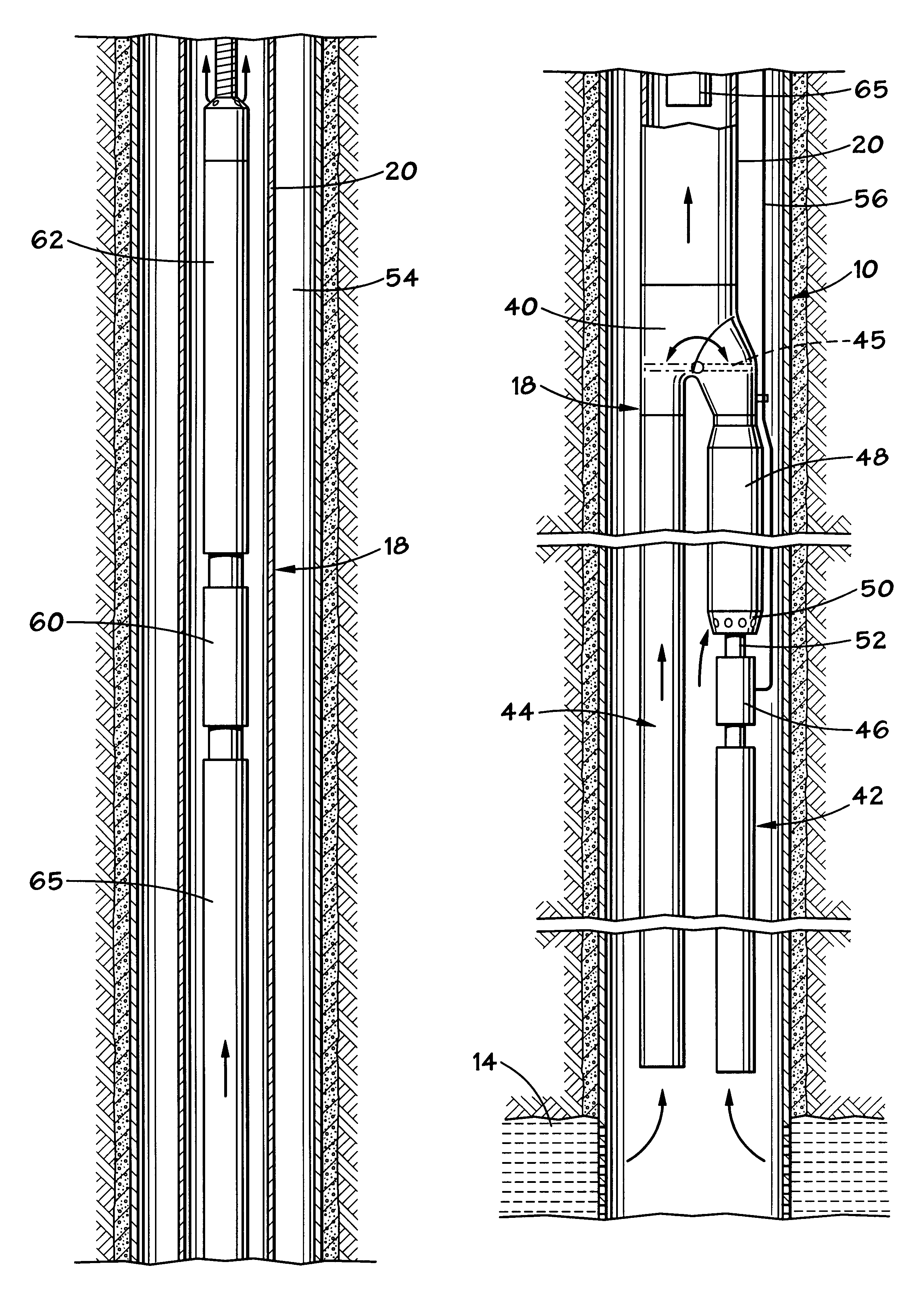
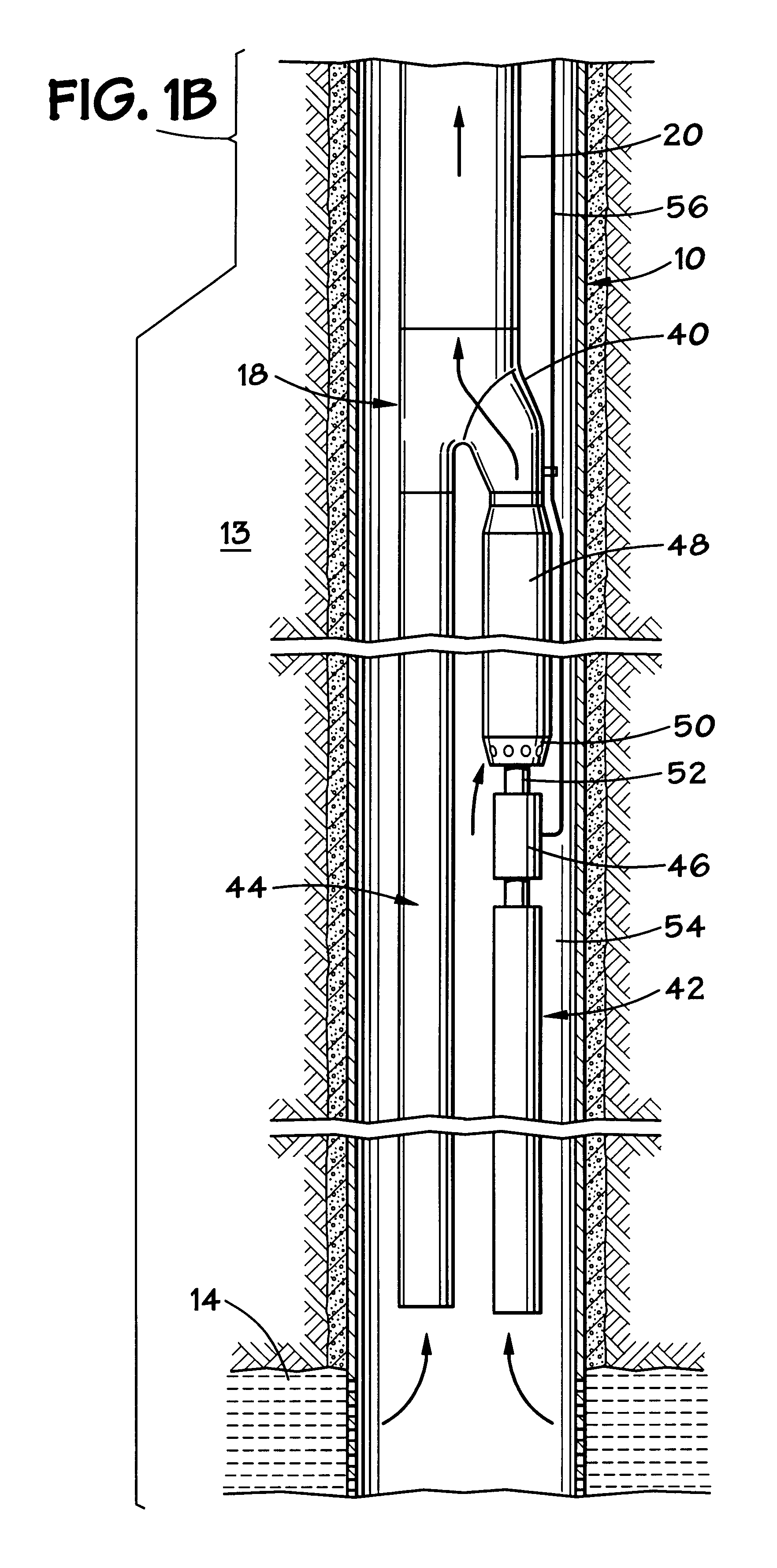
Referring to FIGS. 1A and 1B, there is shown a wellbore 10 that extends downward from a wellhead 12 through rock formations 13 to a hydrocarbon reservoir 14. The wellbore 10 has one or more strings of outer casing (not shown) that are cemented in the wellbore 10. The casing has perforations (not shown) near its lower end allowing flow of well fluid into the wellbore 10 from the earth reservoir 14. A production assembly 18 having a string of production tubing 20 is shown suspended in casing 16. Production tubing 20 is made up of a plurality of tubing sections that are secured together.

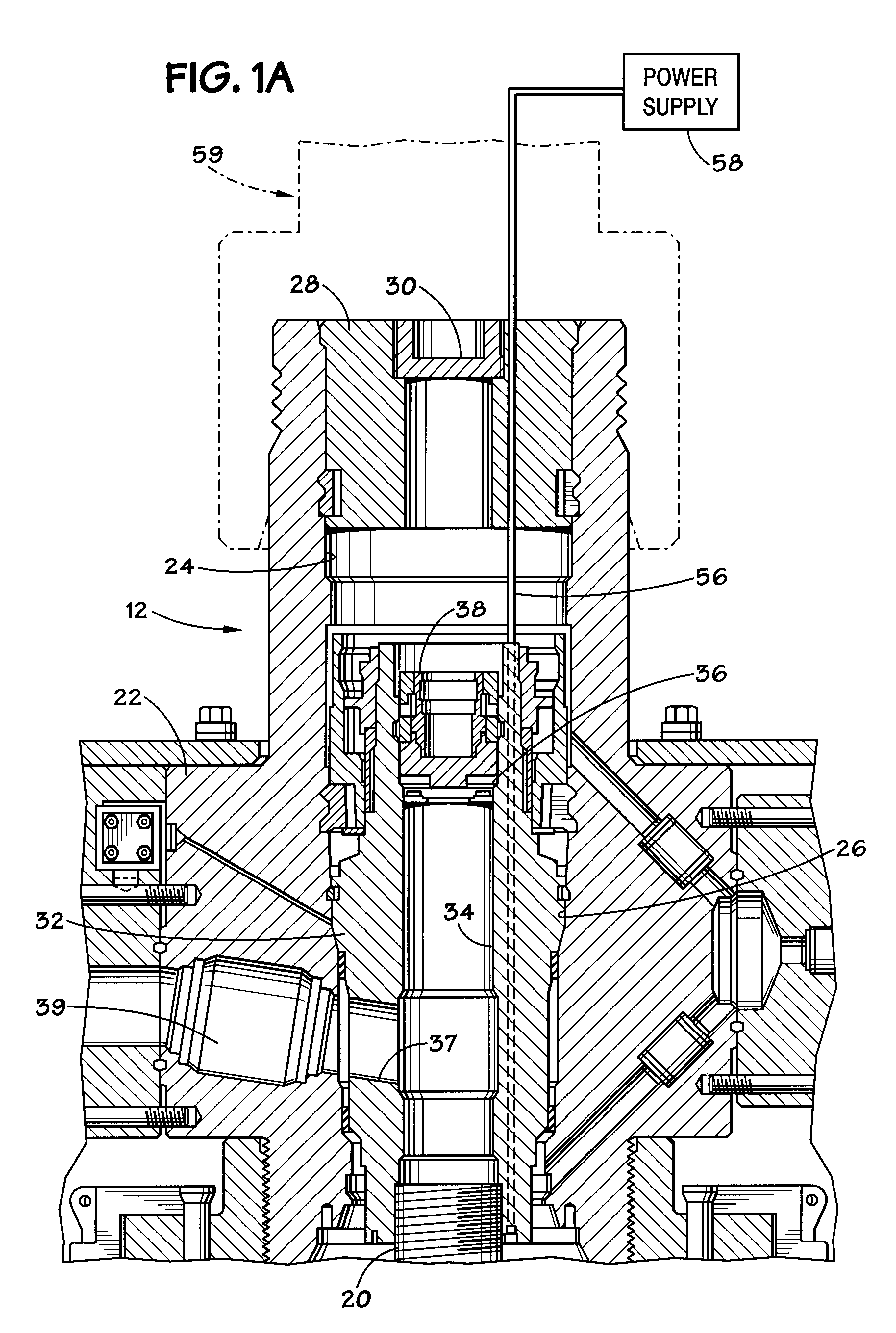
As FIG. 1A depicts, the wellhead 12 has a tree 22 that carries a number of valves and fluid passages, as is known in the art. Tree 22 is known as a "horizontal" tree and is commonly installed subsea. A longitudinal bore 24 is defined within the tree 22 and has presents a seating profile 26. The upper end of the tree 22 is sealed by a removable tree cap 28 that fits in bore 24. The tree cap 28 has a remo...


PUM


Abstract

Methods for staged production from a wellbore include pumps sequentially operated during the life of the well. In described embodiments, production assemblies are used for progressive staged production process in which the production tubing is bifurcated to provide a pair of legs. One of the legs includes a first pump that may be selectively actuated to flow fluid through one of the legs. Means are also provided, including a sliding sleeve and a flapper valve diverter, for blocking production fluid flow through one leg or the other. A second fluid pump is lowered inside of the production tubing to pump fluid after the first pump has failed.

Description

1. Field of the InventionThis invention relates in general to oil well electrical submersible pumps. In particular aspects, the invention relates to the use of coiled tubing-disposed pumps for continuing production after a production tubing-disposed pump has failed.2. Related ArtElectrical submersible pumps ("ESPs") are commonly used in oil and gas wells for producing large volumes of well fluid after natural production has decreased in flow. In conventional methods of production, an ESP would be installed by incorporating it within a string of production tubing or conventional threaded pipe and then lowering the ESP assembly into the well. This process employs the use of a rig and is time consuming. A few ESPs have been installed on coiled tubing for pumping up the annulus surrounding the coiled tubing. Coiled tubing is deployed by a coiled tubing injector from a large reel. There is no need for a rig, and the running time is generally less than for an ESP installed on production t...

Claims


Application Information

Patent Timeline
Patent Type & Authority Patents(United States)
IPC IPC(8): E21B23/00E21B23/12E21B43/12
CPCE21B43/128E21B23/002E21B23/12
Inventor SHAW, CHRISTOPHER KEMPSON
Owner BAKER HUGHES INC
Why Eureka
Try Eureka