Antenna mounting system

a technology for mounting systems and antennas, applied in the direction of antennas, antenna details, antenna adaptation in movable bodies, etc., can solve the problems of affecting the installation of antennas on vehicles, and affecting the installation of antennas

Inactive Publication Date: 2003-01-21
RADIALLLARSEN ANTENNA TECH
View PDF3 Cites 52 Cited by
  • Summary
  • Abstract
  • Description
  • Claims
  • Application Information

AI Technical Summary

Benefits of technology

The present invention provides an antenna mounting system that can be easily attached to a vehicle panel without causing any damage to the paint. The system includes two mounts that are attached to the opposite sides of the panel, a connector that connects the mounts, and a conductive plate that forms a capacitive coupling with the panel. This results in a more efficient and reliable connection for mounting antennas on vehicles.

Problems solved by technology

The technical problem of this patent text is to provide a more efficient and cost-effective method for producing a specific type of chemical compound.

Method used


Image

  • Antenna mounting system
  • Antenna mounting system
  • Antenna mounting system

Examples


Embodiment Construction

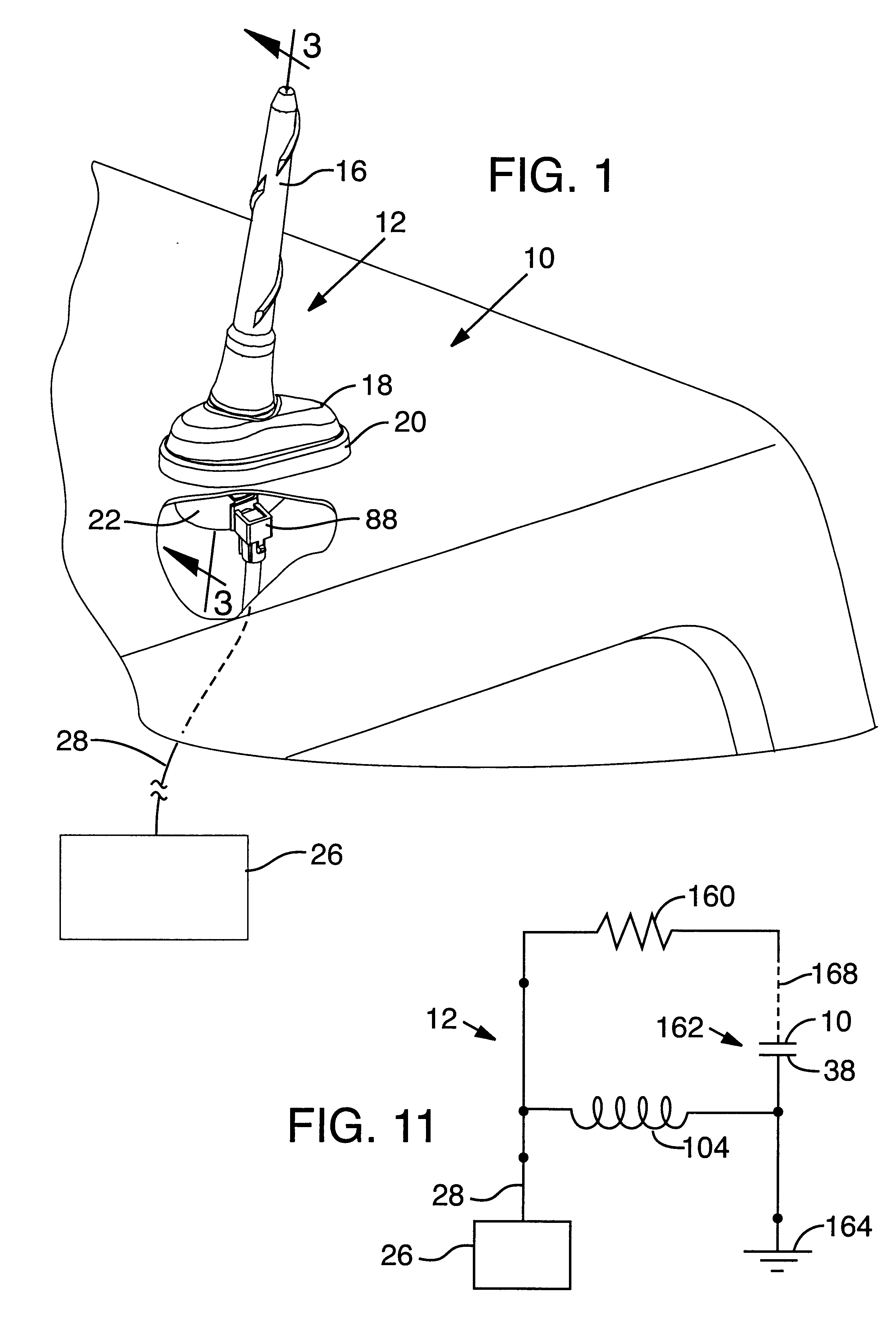
Referring to the drawing, and first more specifically to FIG. 1, at 10 is indicated generally a roof panel of a vehicle on which an antenna mount assembly, or system,12 according to an embodiment of the invention is mounted. A portion of roof panel 10 of the vehicle is broken away to show components of assembly 12 which are mounted on the interior surface of panel 10.

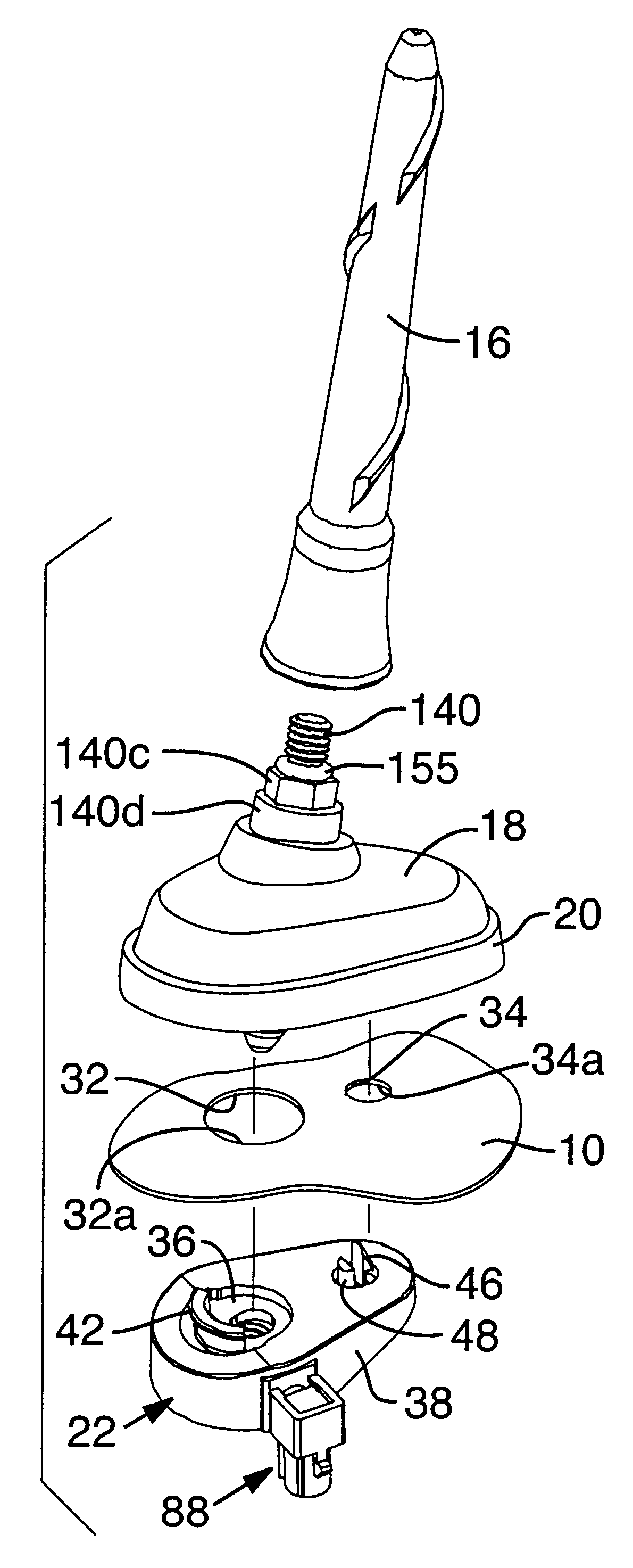
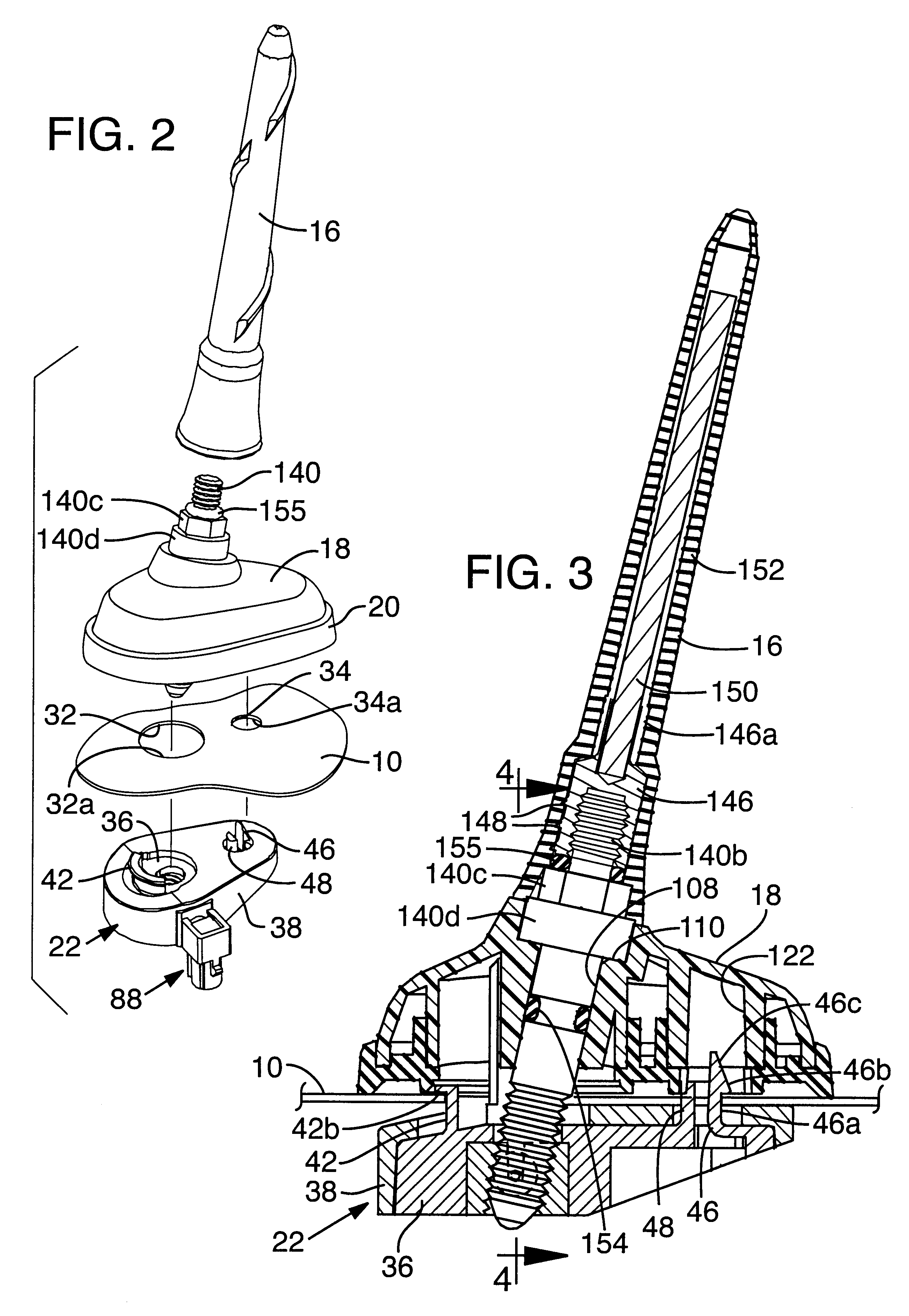
The assembly 12 includes a housing 16 for an antenna radiator, an external mount 18, an elastomeric seal, or boot, 20, and an internal mount 22. Indicated generally at 26 is an electronic telematic system operatively connected through a coaxial cable 28 to antenna system 12, such that signals may be received or radiated by antenna system 12 for the telematic system, 26.

Referring to FIG. 2, roof panel 10 is illustrated as having two circular openings 32, 34 formed therein. Opening 32 is illustrated as having a greater diameter than opening 34. A first edge margin 32a for opening 32 is shown spaced from a second edge marg...


PUM


Abstract

An antenna mounting system includes a first mount having a positioning portion adapted to extend through an opening in a vehicle panel to position and hold the first mount relative to the vehicle panel, a second mount adapted to be disposed adjacent the opposite surface of the vehicle panel, and a connector adapted to couple the first and second mounts to each other. A conductive plate associated with one of the mounts forms a capacitive coupling with the vehicle panel and in conjunction with an inductor or resistor provides a selected resistance to ground. A connector screw in the system has a weakened section which during installation will break should excessive forces be applied thereto, thus to protect other components in the system.

Description


Claims


Application Information

Patent Timeline
Owner RADIALLLARSEN ANTENNA TECH
Why Eureka
Try Eureka