Method for simulating drilling of roller cone bits and its application to roller cone bit design and performance

a technology of roller cone bits and simulation methods, which is applied in the direction of drilling/well accessories, instruments, and using reradiation, etc., can solve the problems of requiring more complex models than fixed cutter bits, significant expense involved in the design and manufacture of drill bits, and inability to accurately model the drilling performance of roller cone bits

Inactive Publication Date: 2003-02-04
SMITH INT INC
View PDF16 Cites 207 Cited by
  • Summary
  • Abstract
  • Description
  • Claims
  • Application Information

AI Technical Summary

Problems solved by technology

Significant expense is involved in the design and manufacture of drill bits.
However, roller cone bits are more complex than fixed cutter bits in that cutting surfaces of the bit are disposed on the roller cones, wherein each roller cone independently rotates relative to the rotation of the bit body about axes oblique to the axis of the bit body.
Therefore, accurately modeling the drilling performance of roller cone bits requires more complex models than for fixed cutter bits.
Currently, no reliable roller cone bit models have been developed

Method used


Image

  • Method for simulating drilling of roller cone bits and its application to roller cone bit design and performance
  • Method for simulating drilling of roller cone bits and its application to roller cone bit design and performance
  • Method for simulating drilling of roller cone bits and its application to roller cone bit design and performance

Examples


third embodiment

In another aspect, the invention provides a method for designing a roller cone bit. In one embodiment, this method includes selecting an initial bit design, calculating the performance of the initial bit design, then adjusting one or more design parameters and repeating the performance calculations until an optimal set of bit design parameters is obtained. In another embodiment, this method can be used to analyze relationships between bit design parameters and drilling performance of a bit. In a third embodiment, the method can be used to design roller cone bits having enhanced drilling characteristics. In particular, the method can be used to analyze row spacing optimization, intra-insert spacing optimization, the balance of lateral forces between cones and between rows, and the optimized axial force distribution among different cones, rows, and cutting elements in the same row.

first embodiment

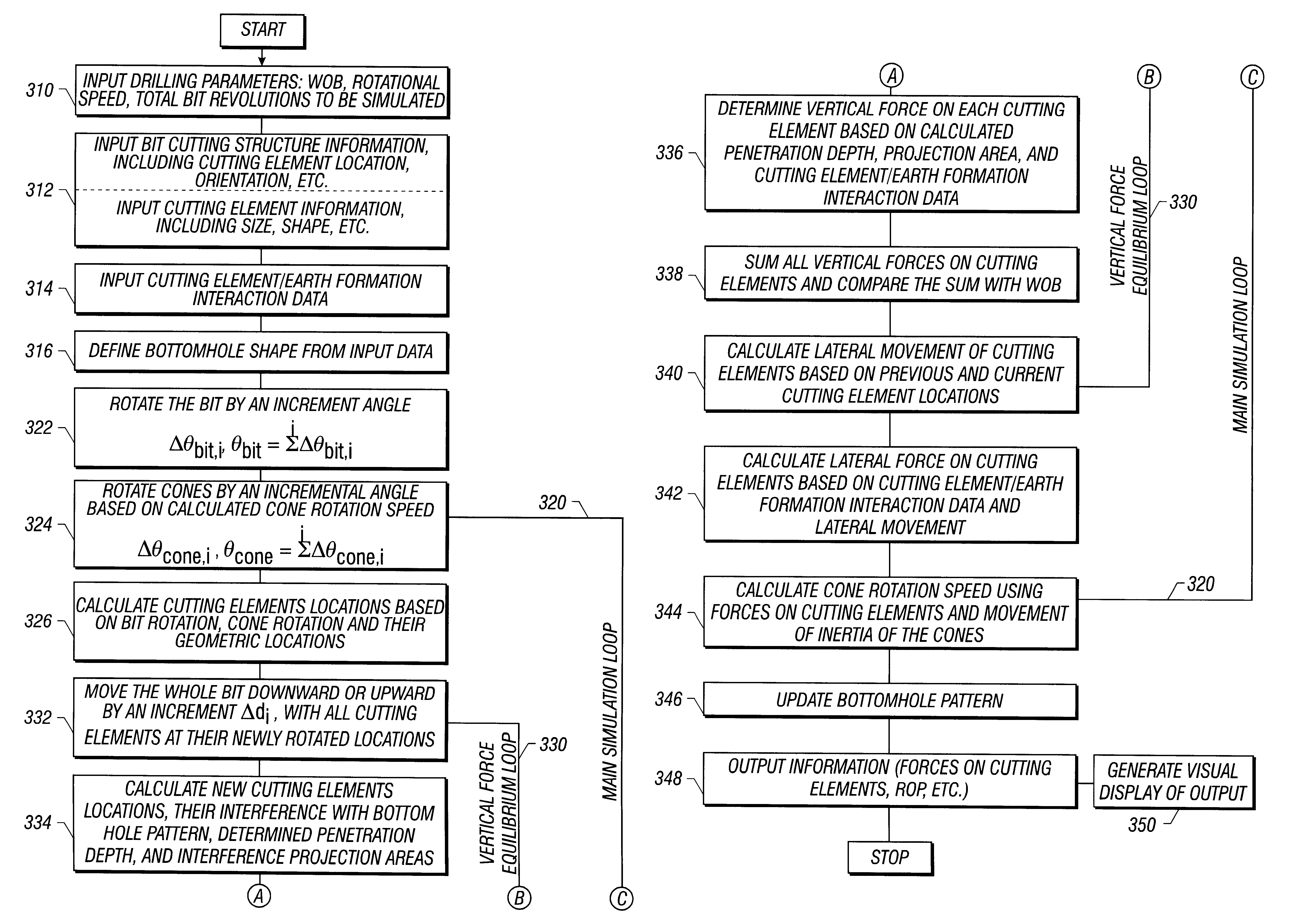
FIGS. 10A and 10B show a flow chart for one embodiment of the invention used to design roller cone drill bits. In this embodiment, the initial input parameters include drilling parameters 410, bit design parameters 412, cutting element / earth formation interaction data 414, and bottomhole geometry data 416. These parameters are substantially the same as described above in FIGS. 3A and 3B.

As shown in FIGS. 10A and 10B, once the input parameters are entered or otherwise made available, the operations in the design loop 460 can be carried out. First in the design loop 460 is a main simulation loop 420 which comprises calculations for incrementally simulating a selected roller cone bit drilling a selected earth formation. The calculations performed in this simulation loop 420 are substantially the same as described in detail above. In the main simulation loop 420, the bit is "rotated" by an incremental angle, at 422, and the corresponding vertical displacement is iteratively determined i...


PUM


Abstract

A method for simulating the drilling performance of a roller cone bit drilling an earth formation may be used to generate a visual representation of drilling, to design roller cone drill bits, and to optimize the drilling performance of a roller cone bit. The method for generating a visual representation of a roller cone bit drilling earth formations includes selecting bit design parameters, selecting drilling parameters, and selecting an earth formation to be drilled. The method further includes calculating, from the bit design parameters, drilling parameters and earth formation, parameters of a crater formed when one of a plurality of cutting elements contacts the earth formation. The method further includes calculating a bottomhole geometry, wherein the crater is removed from a bottomhole surface. The method also includes incrementally rotating the bit and repeating the calculating of crater parameters and bottomhole geometry based on calculated roller cone rotation speed and geometrical location with respect to rotation of said roller cone drill bit about its axis. The method also includes converting the crater and bottomhole geometry parameters into a visual representation.

Description

1. Technical FieldThe invention relates generally to roller cone drill bits, and more specifically to simulating the drilling performance of roller cone bits. In particular, the invention relates to methods for generating a visual representation of a roller cone bit drilling earth formations, methods for designing roller cone bits, and methods for optimizing the drilling performance of a roller cone bit design.2. Background ArtRoller cone rock bits and fixed cutter bits are commonly used in the oil and gas industry for drilling wells. FIG. 1 shows one example of a conventional drilling system drilling an earth formation. The drilling system includes a drilling rig 10 used to turn a drill string 12 which extends downward into a well bore 14. Connected to the end of the drill string 12 is roller cone-type drill bit 20, shown in further detail in FIG. 2. Roller cone bits 20 typically comprise a bit body 22 having an externally threaded connection at one end 24, and a plurality of rolle...

Claims


Application Information

Patent Timeline
IPC IPC(8): E21B10/16E21B10/08E21B41/00
CPCE21B10/16
Inventor HUANG, SUJIANCAWTHORNE, CHRIS E.
Owner SMITH INT INC
Why Eureka
Try Eureka