Partly reflecting optical component and laser source incorporating such a component

a technology of optical components and laser sources, applied in the direction of laser optical resonator construction, instruments, lasers, etc., can solve the problems of device of this type that has not yet been designed and manufactured

Inactive Publication Date: 2003-03-04
EXFO OPTICS SAS
View PDF15 Cites 46 Cited by
  • Summary
  • Abstract
  • Description
  • Claims
  • Application Information

AI Technical Summary

Problems solved by technology

But a device of this type has not been designed yet nor has it been manufactured.

Method used


Image

  • Partly reflecting optical component and laser source incorporating such a component
  • Partly reflecting optical component and laser source incorporating such a component
  • Partly reflecting optical component and laser source incorporating such a component

Examples


Embodiment Construction

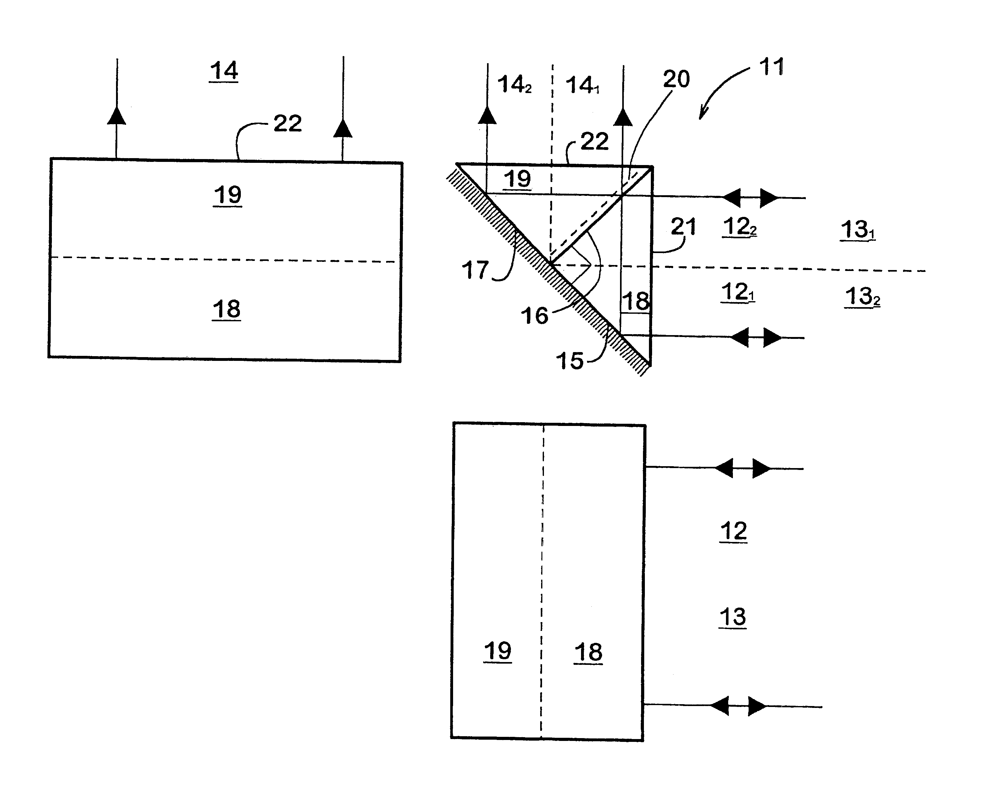
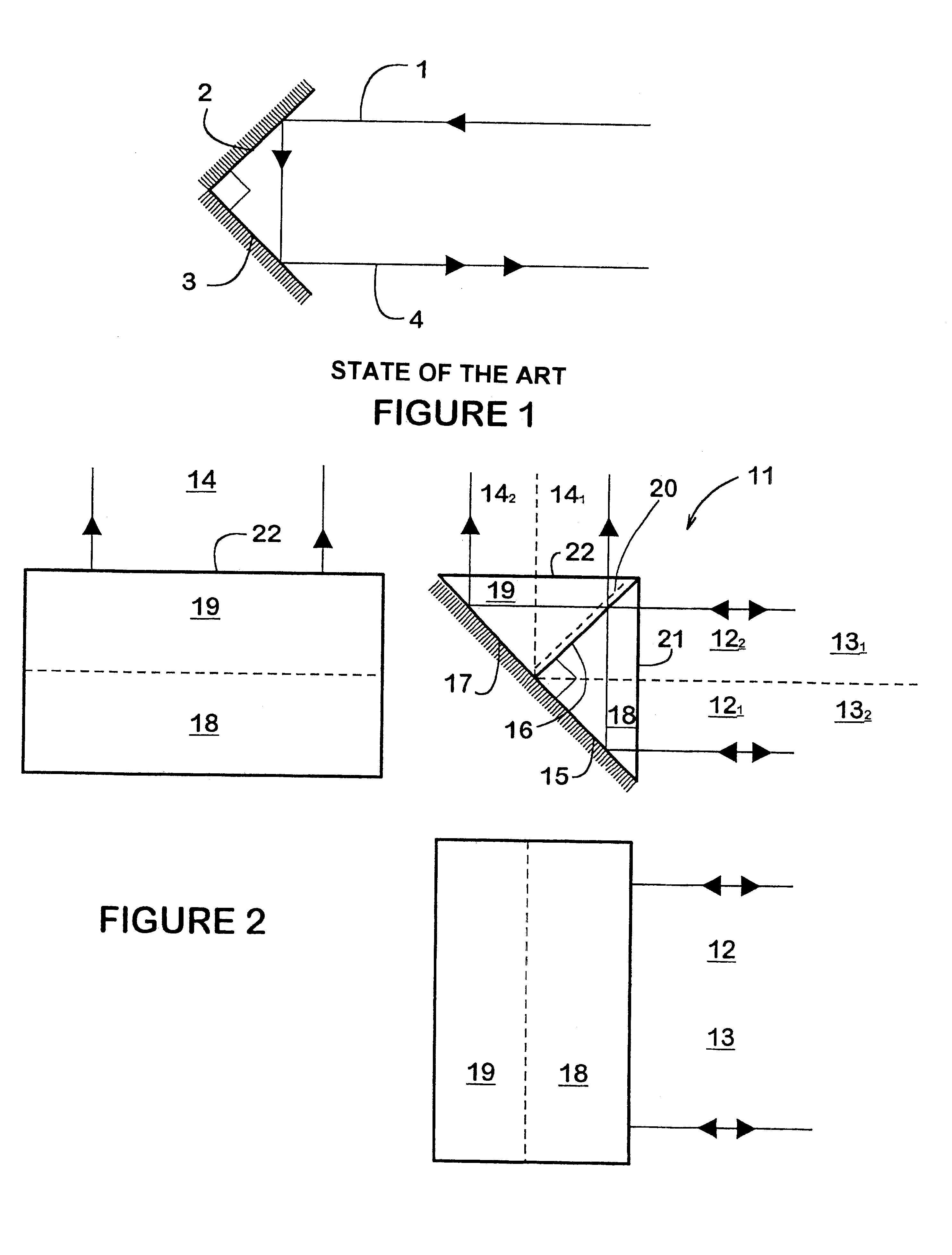
FIG. 2 is therefore is a view of an optical component 11 made with two straight isosceles rectangular prisms.

The incident beam 12 is divided by this optical component 11 into two secondary beams, one beam 13 being reflected in parallel and in an opposite direction with respect to the incident beam 12 and the other beam 14 being transmitted and sent back, in this case in the perpendicular direction with respect to the incident beam 12.

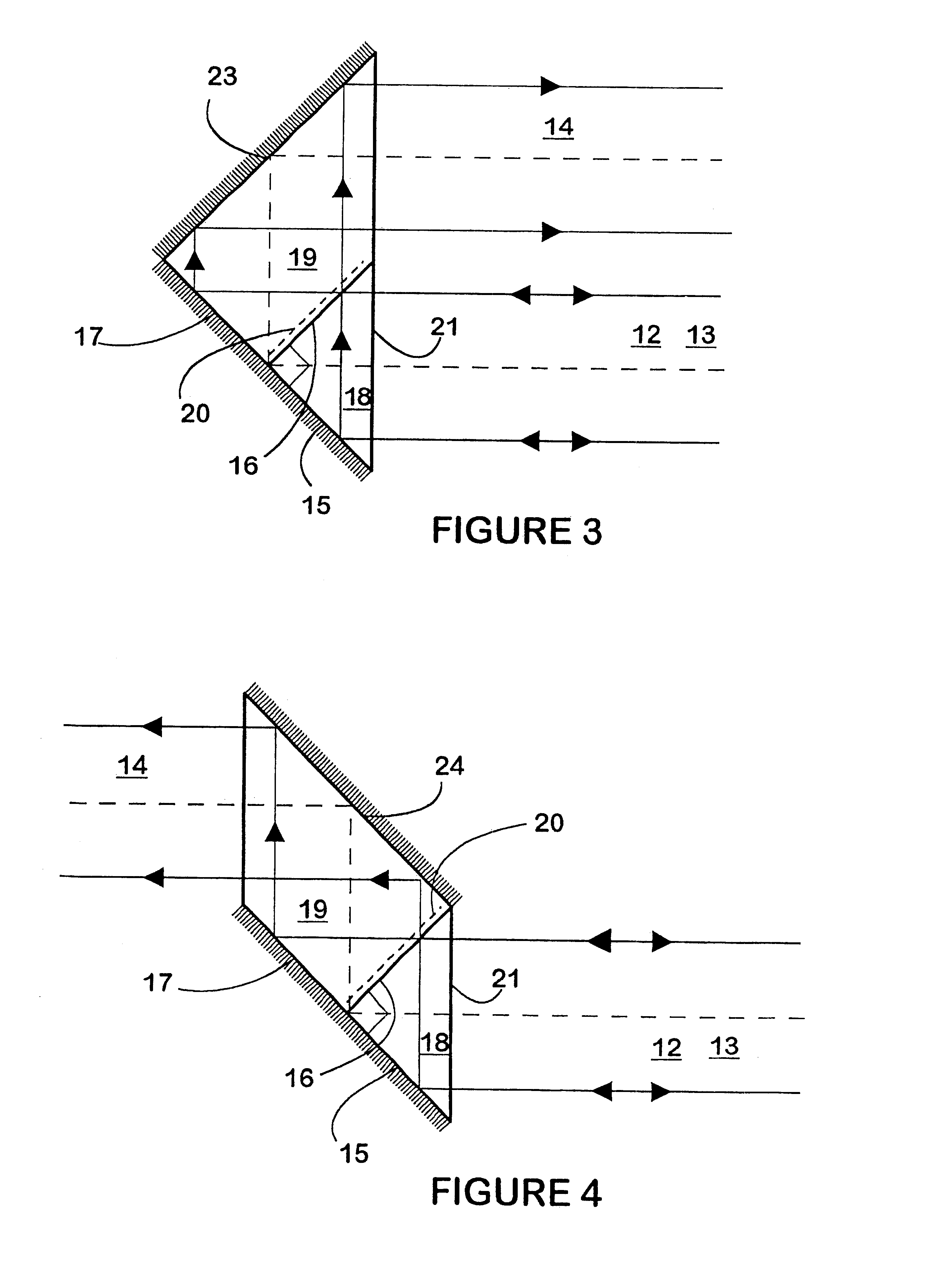
The optical component 11 has a completely reflecting first planar face 15 and a partially reflecting planar face 16 being perpendicular to the first planar face 15.

It also has a completely reflecting third planar face 17 located in the same plane as the first planar face 15.

Thus, the retro-reflected beam 13 is formed from the incident beam 12 with two successive reflections, respectively on both perpendicular faces 15 and 16 of the component 11. It is known, and this has been described referring to FIG. 1 that, in such conditions, the angle formed by th...


PUM


Abstract

A partially reflecting optical component (11) generating, from an incident beam (12), two secondary beams, one of them being reflected (13), the other one being transmitted (14). According to the invention, it comprises a first wholly reflecting planar face (15) and a second partially reflecting planar face (16), the second face being perpendicular to the first one, a third wholly reflecting planar face (17), the first and third faces being in the same plane, this component providing the unidimensional auto-alignment of the reflected beam (13) with the incident beam (12), the respectively transmitted and reflected beams being each formed with two half-beams having matching wave fronts. The invention also relates to an external cavity laser source comprising such a component as a unidimensional auto-aligned reflector.

Description

The present application claims priority under 35 U.S.C. .sctn.119 of French Patent Application No. 99 08400 filed Jun. 30, 1999, the disclosure of which is expressly incorporated by reference herein in its entirety.1. Field of the InventionThe present invention relates to a partially reflecting optical component generating, from an incident beam, two secondary beams, one of them being transmitted, the other one being reflected, and providing the unidimensional auto-alignment of the reflected beam with the incident beam, the respectively transmitted and reflected beams being each formed with two half-beams having matching wave fronts.2. Discussion of Background InformationA component of this type shows indeed significant advantages in many applications such as laser sources with an auto-aligned external cavity. But a device of this type has not been designed yet nor has it been manufactured.By auto-alignment, is meant the property of an optical system for which the properties of the ...

Claims


Application Information

Patent Timeline
Patent Type & Authority Patents(United States)
IPC IPC(8): G02B27/14G02B5/122G02B5/12H01S5/14G02B5/04
CPCG02B5/122H01S5/141G02B27/144H01S5/143
Inventor GRAINDORGE, PHILIPPE
Owner EXFO OPTICS SAS
Why Eureka
Try Eureka