Lens-eye model and method for predicting in-vivo lens performance

a lens performance and lens model technology, applied in the field of lens performance prediction and lens performance prediction in vivo, can solve problems such as difficult prediction of soft contact lens performance in vivo, for exampl

Inactive Publication Date: 2003-09-30
BAUSCH & LOMB INC
View PDF6 Cites 88 Cited by
  • Summary
  • Abstract
  • Description
  • Claims
  • Application Information

AI Technical Summary

Benefits of technology

The representative cornea 12 is constructed from an optically and anatomically transparent, machineable material such as polymethylmethacrylate (PMMA). Alternatively, similarly characteristic materials may be used, such as glass, polycarbonate, polystyrene, styrene acrylonitrile (SAN), topaz, cyclo-olefin polymers, CR-39, amorphous polyolefin, and others preferably having dispersion characteristics similar to those of an actual eye. The use of advantageous materials provide corneal rigidity, while surface shape can easily be imparted to the material by various known techniques. For example, the anterior corneal surface 14 can be machined by a diamond turning process well known to those skilled in the art to impart a surface shape representative of an actual cornea. Alternatively, based upon corneal curvature and shape data characteristic of the general population, a standard or typical surface shape can be imparted to the anterior corneal surface 14. It will be appreciated that other techniques may be used to create a desired shape for the anterior corneal surface. For example, spherical, aspheric, toric, or custom shapes can be imparted by techniques including laser ablating the surface, cast molding the surface, thermally molding the surface, grinding and polishing, and by other known techniques.
An optional enclosure 24 surrounds the anterior corneal surface 14 and preferably provides the eye model system with a controlled temperature and humidity environment through temperature / humidity controller 55. This is advantageous, for instance, when the optic under test is a soft contact lens 30 The environment in which the contact lens 30 resides is maintained to minimize the evaporation of tear layers 26, 28 and the dehydration of the contact lens 30. For example, since 66% of the volume of a hydrated Soflens 66.RTM. (Bausch & Lomb, Rochester, N.Y.) soft contact lens contains water, the humidity inside the enclosure 24 is maintained at at least 66%, so that the contact lens 30 will be stable and not dry out. In addition, the rate of evaporation of the tears 26, 28 will be significantly reduced. The humidity may range between 0-100%, and the temperature may be in a range to simulate actual environmental conditions.
It will be appreciated that the retinal surface 18 may be constructed to scatter or reflect the light 32 back through the model eye system into a diagnostic measurement device 42, or, to transmit the light through the retinal surface if it is made transparent. Alternatively, illustrated with reference to FIG. 3, the retinal surface 18 is shown having a pinhole aperture 72. The model eye system can conveniently be back-illuminated through the pinhole aperture 72 with the light emerging from the top of the eye model system.

Problems solved by technology

It has long been a challenge in the field of vision correction to be able to predict the subjective response of a patient prior to actually altering the patient's vision, either surgically or by external means such as spectacles or contact lenses, for example.
Moreover, soft contact lens performance in-vivo, for example, is difficult to predict due to changes in the lens' surface shapes caused by the actual, variable, corneal contours of people's eyes, as compared to the manufactured shape of the lens.

Method used


Image

  • Lens-eye model and method for predicting in-vivo lens performance
  • Lens-eye model and method for predicting in-vivo lens performance
  • Lens-eye model and method for predicting in-vivo lens performance

Examples


Embodiment Construction

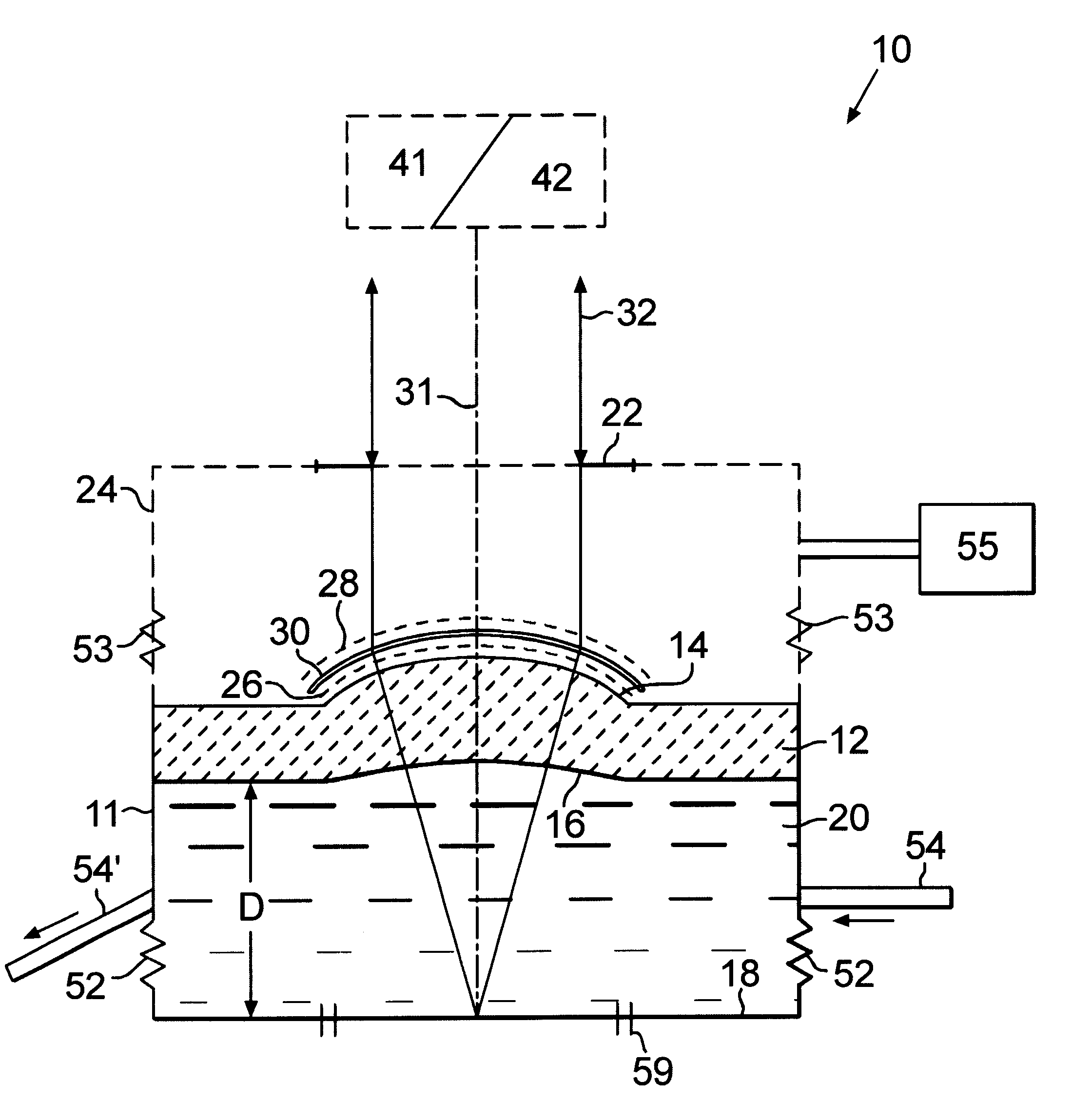
A schematic drawing of a model eye system 10 according to an embodiment of the invention is shown in FIG. 1. The model eye system 10 has a structural housing 11 and includes a representative cornea 12 having an anterior surface 14 and a posterior surface 16. A retinal surface 18 is located posterior to the posterior corneal surface 16 at a distance, D. A dispersion medium 20 is located between the posterior corneal surface 16 and the retinal surface 18. An optional enclosure 24 (shown in dotted lines) having a variable aperture 22 for light entry and exit, surrounds the anterior corneal surface 14 to provide a controlled environment as necessary or desired for the measurement being conducted. As illustrated, a soft contact lens 30 is located on the anterior corneal surface 14.

The housing 11, in the region of the dispersion medium 20, is shown having flexible joints 52 that allow the separation distance D between the cornea 12 and the retinal surface 18 to be adjusted for focus error...


PUM

PropertyMeasurementUnit
humidityaaaaaaaaaa
humidityaaaaaaaaaa
flexibleaaaaaaaaaa

Abstract

An eye model system for remotely predicting the in-vivo performance of a vision altering optic includes a representative cornea, a dispersion medium, and a retinal surface. The corneal surfaces provide anatomical shape, optical power, and higher order aberration content. The dispersion medium mimics chromatic dispersion in an actual eye. The retinal surface is moveable to provide selected defocus. A humidity and temperature enclosure may be provided. Model eye elements can be tilted or decentered to simulate actual conditions. An associated method for remotely measuring the performance of a vision altering optic to predict its performance in-vivo includes making topography, wavefront, interferometry, PSF, MTF, or other optical and / or physical measurements of the model eye system with and without the optic in combination.

Description

1. Field of the InventionThe present invention relates generally to methods and apparatus for measuring the performance of an optical lens, and more particularly to a model eye system for predicting the in-vivo performance of a vision altering optic, and methods related thereto.2. Description of Related ArtNumerous descriptions of various eye models are found in the literature. Eye models are helpful for many reasons, including designing contact lenses, modeling vision under various conditions such as refractive surgical procedures, contact lens or spectacle wear, and near vision, for biometric applications, and many others.It has long been a challenge in the field of vision correction to be able to predict the subjective response of a patient prior to actually altering the patient's vision, either surgically or by external means such as spectacles or contact lenses, for example. Moreover, soft contact lens performance in-vivo, for example, is difficult to predict due to changes in ...

Claims


Application Information

Patent Timeline
Patent Type & Authority Patents(United States)
IPC IPC(8): A61B3/00G09B23/28G09B23/00
CPCG09B23/28
Inventor ALTMANN, GRIFFITH E.
Owner BAUSCH & LOMB INC
Why Eureka
Try Eureka