Method and apparatus for winding spooled materials

a technology of spooled materials and winding methods, which is applied in the direction of ornamental textile articles, transportation and packaging, shop accessories, etc., can solve the problems of kinks in the ribbon, the radius of curling is difficult to maintain constant, and the curl achieved using such prior art methods is difficult to precisely control

Inactive Publication Date: 2007-03-22
DATO KIM J +1
View PDF58 Cites 1 Cited by
  • Summary
  • Abstract
  • Description
  • Claims
  • Application Information

AI Technical Summary

Benefits of technology

[0017] In a fourth aspect of the invention, an apparatus for winding the material onto one or more spools is disclosed. In one embodiment, the device comprises at least one feed or supply spool containing unconditioned ribbon, a conditioning device which is laterally positioned with respect to at least one selectable take-up spool, and a motive source for driving the take-up spool. The unconditioned ribbon is taken from the supply spool, passed through the conditioner for curling / twisting, and then wound onto the take-up spool in a generally helical pattern which crosses back and forth along the longitudinal axis of the take-up spool. The selected diameter of the spool, in conjunction with the helical lay pattern, aids in maintaining the curl and twist of the ribbon after conditioning. When fully loaded, the take-up spool is removed and an empty spool put in its place. In a second embodiment, the apparatus includes a plurality of supply spools, conditioning devices, and take-up spools such that more than one spool can be wound in parallel. In a third embodiment, the apparatus further includes a tensioning device for controlling the tension of the material as it passes through the conditioning device, and detecting breakage of the material during conditioning / winding.
[0020] In another embodiment, the curling element further includes a resistive heating element disposed in close proximity to curling surface of the element, thereby elevating the temperature of the curling surface such that curl is more readily imparted to the ribbon as it traverses the curling surface.

Problems solved by technology

Furthermore, it is noted that the curl achieved using such prior art methods is difficult to maintain constant, and the radius of curl is difficult to control precisely.
Also, kinks can occur in the ribbon while curling which make a given piece of curled ribbon non-uniform in appearance.
This reduces the satisfaction provided to the user as well as any other individuals viewing the ribbon.
There is also the labor involved with locating the scissors or other stripping device, and performing the stripping operation.
Also, there is some potential for personal injury from the sharpened blade of the scissors or other stripping device, or heat from a curling device.
Additionally, the “twist” present in the ribbon is difficult to maintain uniform.
If the curl / twist is non-uniform, then the helix formed by the ribbon when free-standing may be non-uniform as well, thereby resulting in an undesirable appearance.
To achieve such results using discretely wound helices would be prohibitively time consuming and tedious, since the user would be required to somehow concentrically or co-extensively wind the individual helices together after they were unwound from their respective spools.
However, the foregoing inventions do not provide a mechanism by which the curled ribbon is ultimately stored in the desired helical geometry of substantially similar radius to that imparted to the ribbon during curling so as to maintain its shape to maximum degree practicable.
Similarly, none of the foregoing prior art references disclose a method or apparatus for accomplishing concentric or co-extensive (juxtaposed) winding of different types or colors of decorative ribbon or other spooled materials.

Method used


Image

  • Method and apparatus for winding spooled materials
  • Method and apparatus for winding spooled materials
  • Method and apparatus for winding spooled materials

Examples


Embodiment Construction

[0035] Reference is now made to the drawings wherein like numerals refer to like parts throughout.

[0036] It is noted that while the following description is cast primarily in terms of an apparatus and method for winding decorative ribbon(s) onto one or more spools, the concepts and methods of the present invention may be used with other types of materials and in other applications with equal success. The method and apparatus of the invention can conceivably be applied to other “coiled” materials such as, for example, telephone cord. Accordingly, the invention is in no way meant to be limited to decorative ribbon; rather, its scope is defined by the claims appended hereto.

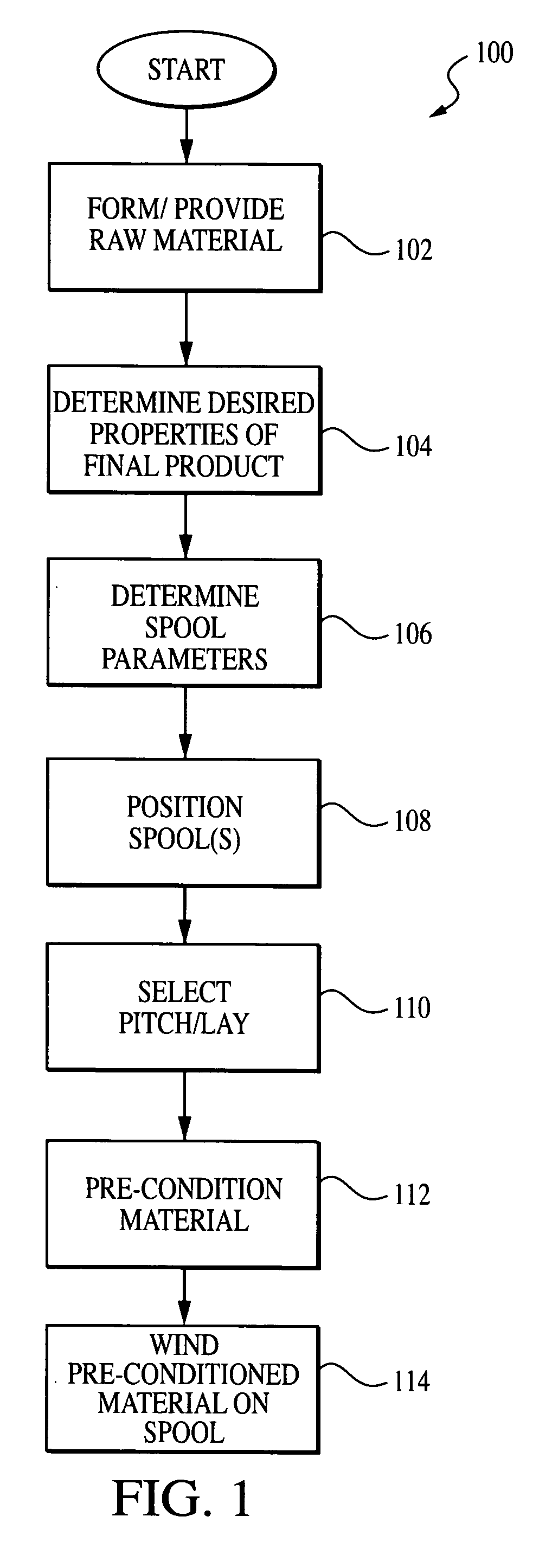
[0037] Referring now to FIG. 1, one embodiment of the method 100 of conditioning and winding material onto a spool according to the invention is described. As shown in FIG. 1, the method 100 comprises first providing or forming the “raw” or unconditioned material in step 102. In the illustrated embodiment, such un...


PUM

PropertyMeasurementUnit
lengthaaaaaaaaaa
widthaaaaaaaaaa
lengthaaaaaaaaaa

Abstract

A method and apparatus for winding conditioned material onto a spool so as to maintain its desirable properties. In one embodiment, decorative ribbon is conditioned using a curling device and wound onto an elongated spool having a predetermined radius in an alternating, helical lay pattern so as to maintain the curl of the ribbon, and permit easy removal and storage thereof. In a second embodiment, two or more different types or colors of ribbon are wound either concentrically or in juxtaposed orientation onto the same spool. An apparatus for winding one or more of the aforementioned spools is also disclosed. A multi-spool dispenser for the curled ribbon is further described.

Description

[0001] This application claims priority to U.S. Provisional Patent Application Ser. No. 60 / 167,258 filed Nov. 22, 1999, entitled “Method And Apparatus For Winding Spooled Materials.”BACKGROUND OF THE INVENTION [0002] 1. Field of the Invention [0003] The present invention relates to wound or spooled materials, including decorative ribbon. [0004] 2. Description of the Related Art [0005] Different types of wound or spooled materials are presently in use. For example, decorative ribbon, string, thread, tape, and the like are characteristically wound in a rotary fashion onto a spool to facilitate space-efficient storage and access to the material by a user. Winding these materials onto the spool is typically accomplished using a machine which rotates the receiving spool and the material delivery device (which feeds the material onto the spool) in relation to one another such that the material is deposited in generally concentric or helical layers. The resulting product is a spool of mate...

Claims


Application Information

Patent Timeline
Patent Type & Authority Applications(United States)
IPC IPC(8): B65H16/06B65H75/18B65H18/10B65H54/02B65H54/10B65H55/00D04D9/06
CPCA47F13/00B65H18/10B65H49/32B65H54/026B65H54/10B65H55/00D04D9/06B65H75/182B65H2301/5121B65H2301/5143B65H2701/18444B65H2701/37B65H2701/528B65H55/005
Inventor DATO, KIM J.DATO, JAMES E.
Owner DATO KIM J
Why Eureka
Try Eureka