Custom contact lens molding system and methods

a contact lens and molding system technology, applied in the field of custom contact lens molding system and methods, can solve the problems of prohibitively thin corneal tissue thickness in the center of the cornea, adversely affecting the imaging properties of the eye, and not without limitations, and achieve the effect of preventing further deformation

Inactive Publication Date: 2005-12-01
NORTHWESTERN UNIV +1
View PDF9 Cites 89 Cited by
  • Summary
  • Abstract
  • Description
  • Claims
  • Application Information

AI Technical Summary

Benefits of technology

[0011] In a preferred embodiment, a custom contact lens is formed by deforming a moldable blank of material. For example, a disc-shaped piece of molded material may be placed within the mold so that at least one surface of the material contacts a first side of a deformable surface within the mold. An array of actuators, which may be electrically, pneumatically or hydraulically controlled, is disposed in contact with a second side of the deformable surface to impose localized deflections on the deformable surface. By varying the magnitude and location of the localized deflections created by the array of actuators, a predetermined surface contour may be impressed onto the moldable material via the deformable surface, including any required asymmetry. The material then may be hardened, cured, or otherwise treated to help retain the impressed surface contour and to prevent further deformation.

Problems solved by technology

Many other aberrations may adversely impact the imaging properties of an eye.
Although this procedure has resulted in some success, it is not without limitations.
If it is desired to produce a long radius surface on a relatively short radius cornea, the thickness of the corneal tissue in the center of the cornea may become prohibitively thin.
Other limitations may arise at the transition zone where a newly sculpted surface joins a native surface.

Method used


Image

  • Custom contact lens molding system and methods
  • Custom contact lens molding system and methods
  • Custom contact lens molding system and methods

Examples


Embodiment Construction

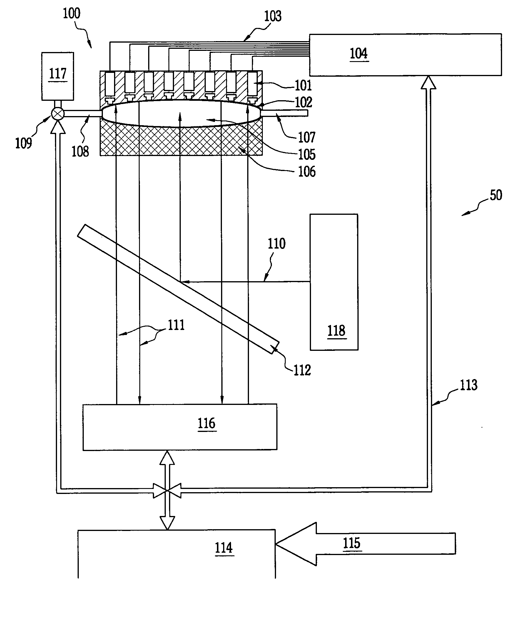
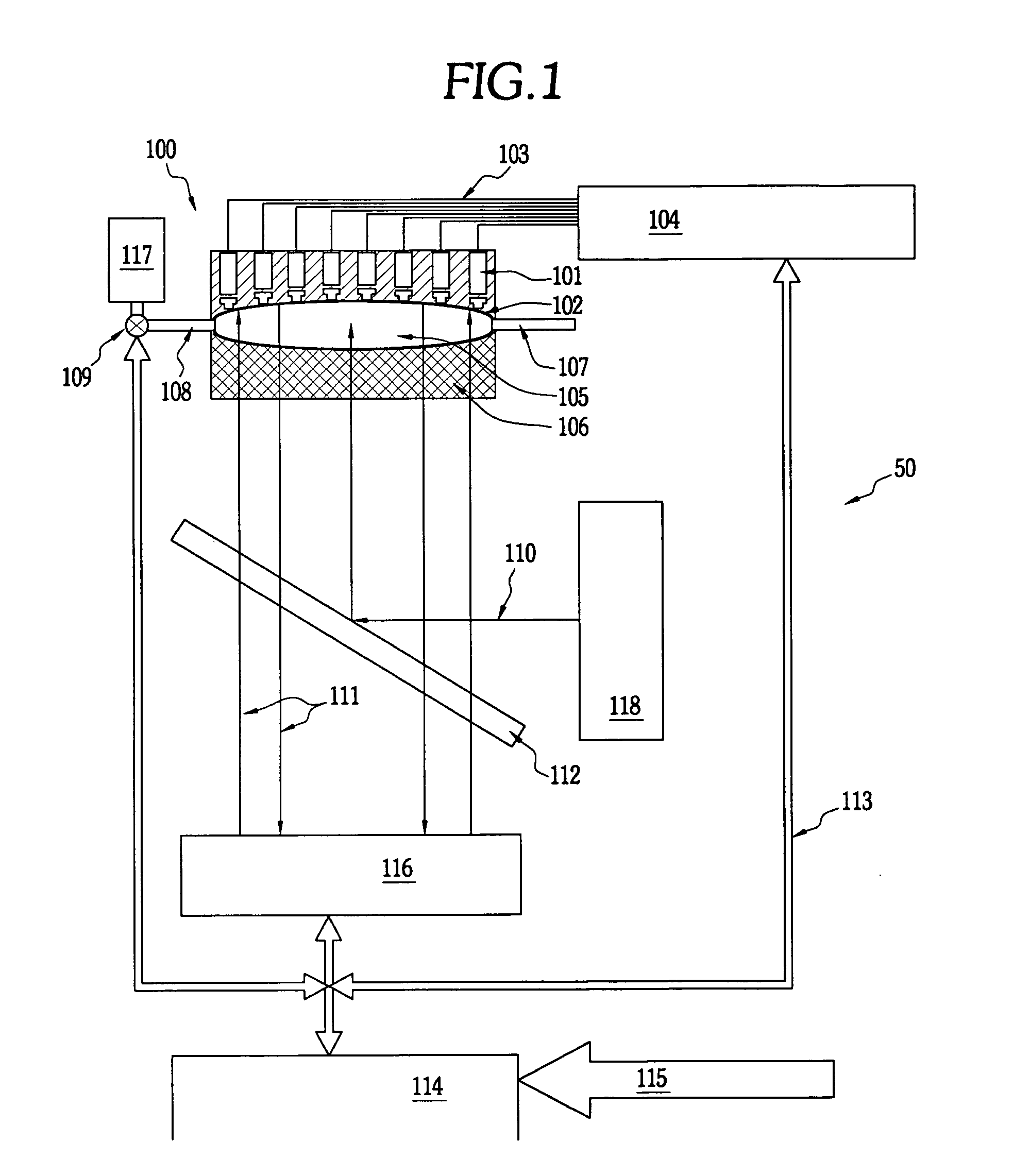
[0021] The present invention is directed to systems and methods for forming custom lenses, and in particular, for forming contact lenses suitable for treating astigmatism and other higher order aberrations. Commercially available contact lens designs often provide only a limited degree of customization. The system and methods of the present invention permit enhanced customization of contact lenses, at lower cost and with greater ease-of-use than may be currently achievable.

[0022] Prior to fabricating a custom contact lens for a particular patient, the patient's vision deficiency must be assessed. Apparatus and methods for making this assessment are known, such as described in U.S. Pat. No. 6,598,975 to Liang, et al., which is hereby incorporated by reference in its entirety. The prescriptive information obtained using a wavefront measurement device then may be used as input for the custom contact lens fabrication system of the present invention. While this information generally ori...


PUM

PropertyMeasurementUnit
wavelengthsaaaaaaaaaa
surface contouraaaaaaaaaa
moldableaaaaaaaaaa

Abstract

Apparatus and methods for manufacturing custom contact lenses and molds is provided wherein a reconfigurable mold has a cavity including deformable surface that is deformed by an array of actuators to define a specified surface contour that will result in a desired wavefront. The specified surface contour may be imparted to moldable material deposited in the cavity, and the array of actuators may be repositioned to optimize the vision correction provided by the custom contact lens. Methods of using the reconfigurable mold to manufacture custom contact lens molds also are provided.

Description

FIELD OF THE INVENTION [0001] The present invention relates to apparatus and methods for producing custom contact lenses or other optical elements. More particularly, the present invention relates to a molding system including at least one deformable surface having localized deflections controlled by an array of actuators. BACKGROUND OF THE INVENTION [0002] The use of contact lenses to correct for imperfect vision is now commonplace, and there are a vast number of lens products available to the public that are typically quite inexpensive. Among these products are “toric” contact lenses, designed to correct the common visual defect of astigmatism. This aberration arises from an asymmetry of the curvature of the cornea. An astigmatic surface may be described by two radii of curvature, denoted as major and minor radii, and the orientation of the two axes. [0003] Many other aberrations may adversely impact the imaging properties of an eye. Such aberrations may conveniently be described ...

Claims


Application Information

Patent Timeline
Patent Type & Authority Applications(United States)
IPC IPC(8): B29C33/30B29D11/00G02C7/04
CPCB29D11/00134B29C33/308B29D11/00951B29D11/00557B29D11/00548
Inventor ESCH, VICTOR C.
Owner NORTHWESTERN UNIV
Why Eureka
Try Eureka