
Structured surface articles containing geometric structures with compound faces and methods for making same

a technology of geometric structure and surface, applied in the field of structured surface articles, can solve the problems of inability to make small cube corner elements, inability to meet the needs of small cubes,

Inactive Publication Date: 2003-04-01
3M INNOVATIVE PROPERTIES CO
View PDF45 Cites 115 Cited by
  • Summary
  • Abstract
  • Description
  • Claims
  • Application Information

AI Technical Summary

Benefits of technology

In the drawings, the same reference symbol is used for convenience to indica

Problems solved by technology

Each of these techniques has its own benefits and limitations.
However, such techniques are impractical for making small cube corner elements (e.g. those having a cube height less than about 1 millimeter) because of the large number of pins and the diminishing size thereof required to be precisely machined and then arranged in a bundle to form the mold.
However, design flexibility suffers relative to that achievable by pin bundling.
However, a significant drawback to direct machining techniques has been reduced design flexibility in the types of cube corner geometries that can be produced.

Method used


Image

  • Structured surface articles containing geometric structures with compound faces and methods for making same
  • Structured surface articles containing geometric structures with compound faces and methods for making same
  • Structured surface articles containing geometric structures with compound faces and methods for making same

Examples


Embodiment Construction

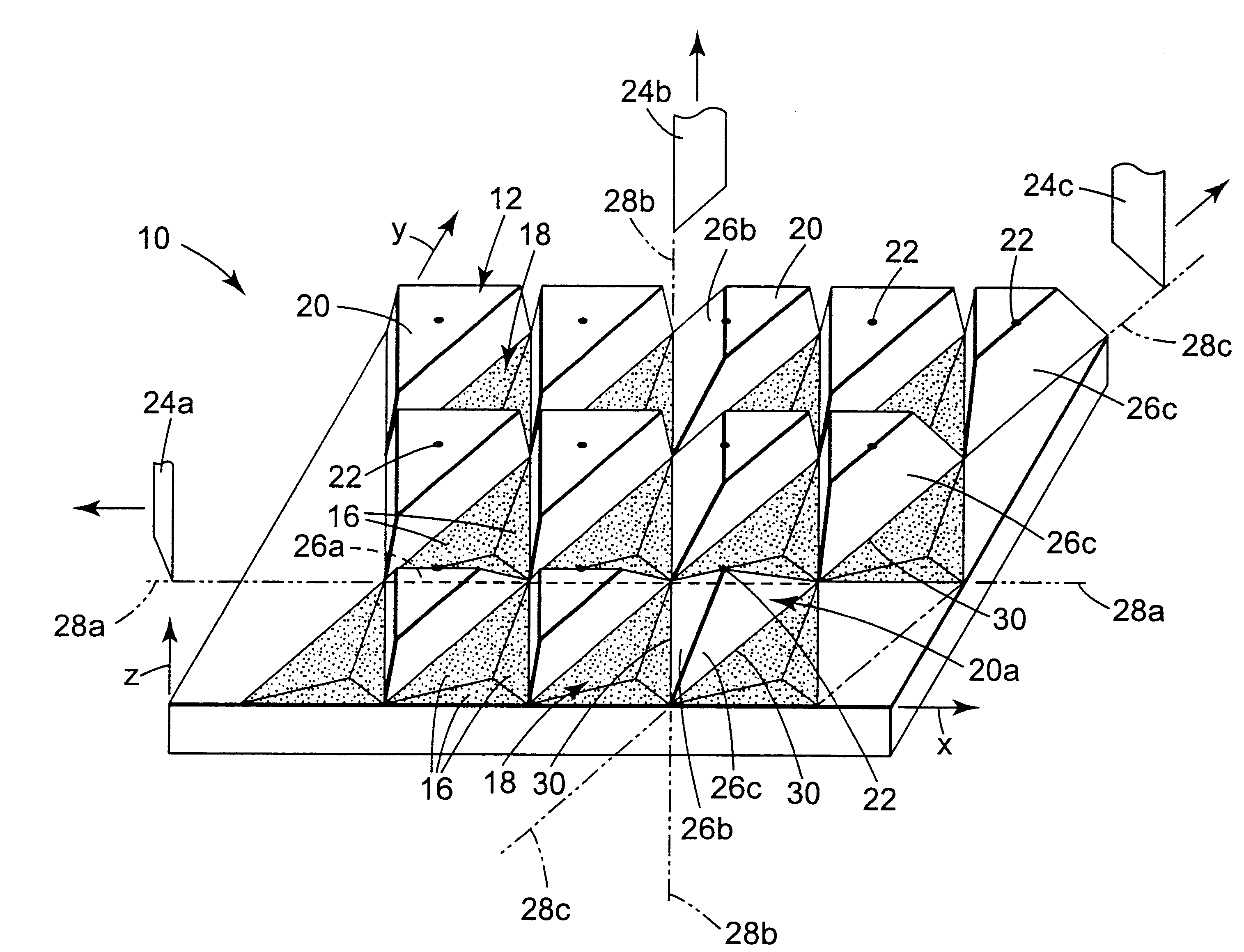
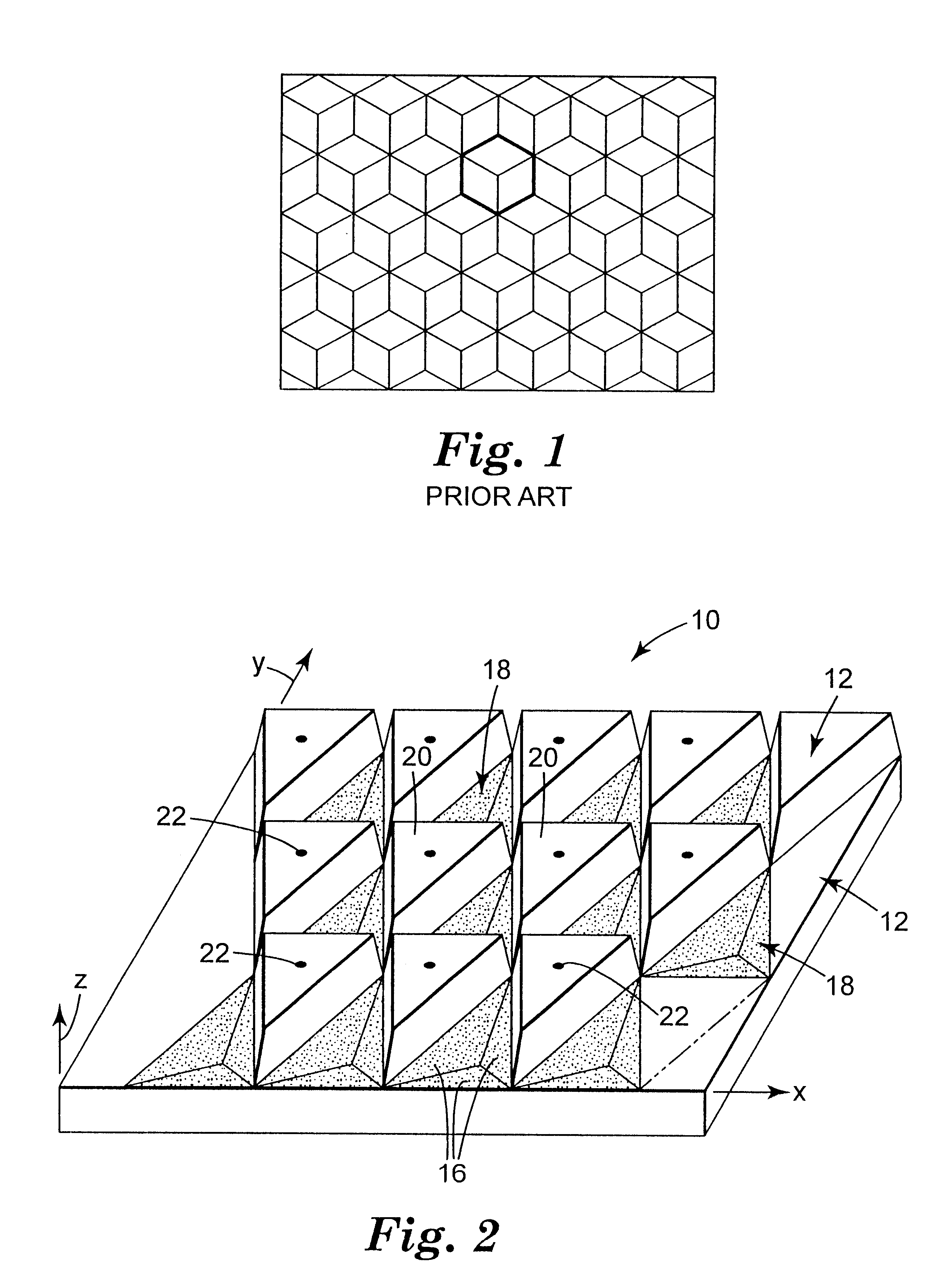
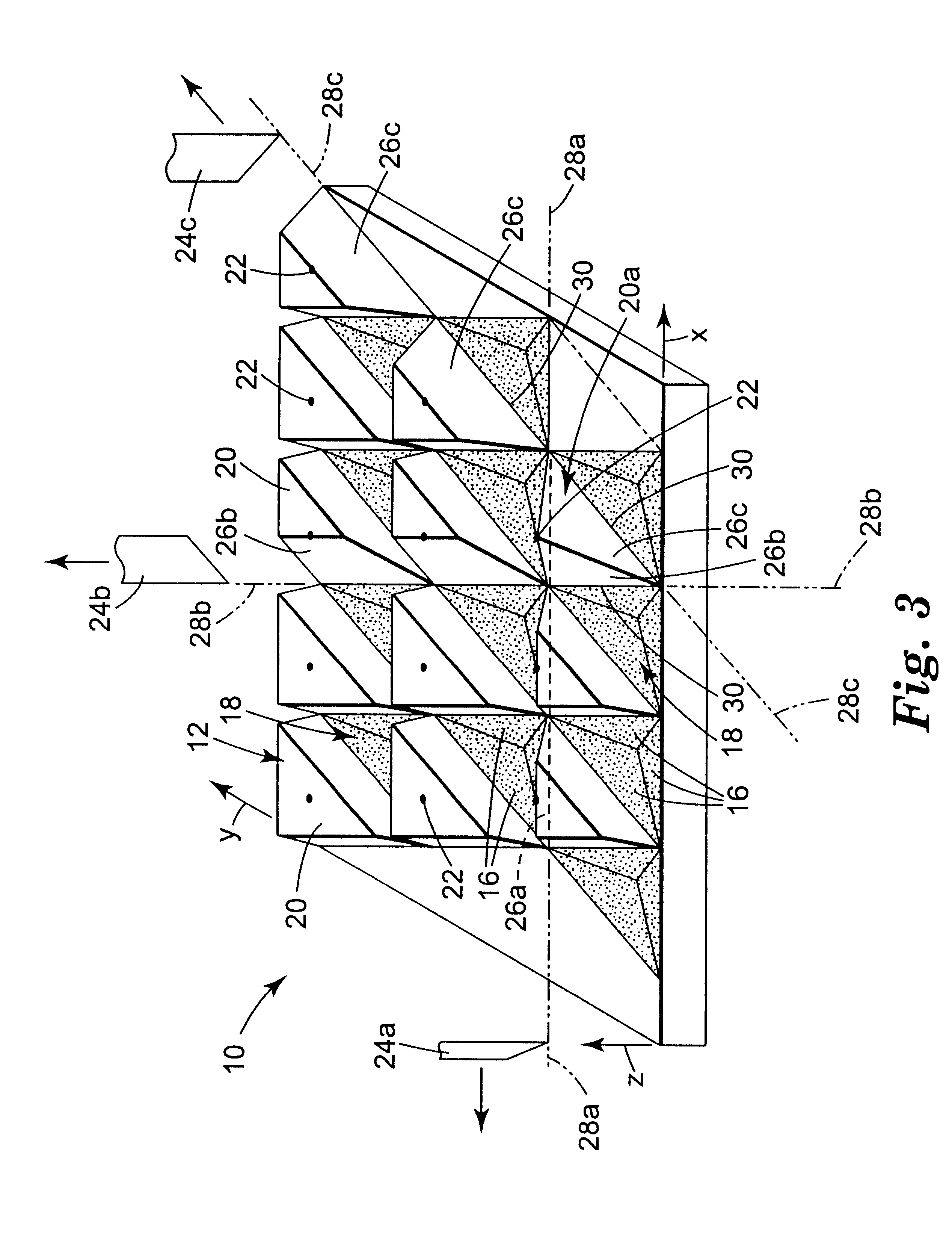
In FIG. 2, a prepared substrate 10 is shown enlarged in perspective view. A description of how prepared substrate 10 can be fabricated is deferred for later discussion below. Substrate 10 has a structured surface 12 that generally defines a reference plane x-y. Structured surface 12 includes faces 16 arranged in groups of three that form cube corner cavities 18. Interspersed between cube corner cavities 18 on structured surface 12 are protrusions 20. The protrusions as shown each have three side surfaces and a top surface, and are of triangular cross section. Depending on the procedure used to make the prepared substrate, the side surfaces of the protrusions 20 can be inclined to a greater or lesser extent away from the vertical. In the figure, reference points 22 located on the top surfaces of protrusions 20 are shown for ease of description. It is not critical that the tops of protrusions 20 pass through the locations marked by reference points 22, nor is it critical that the side...


PUM


Abstract

A process for making molds for retroreflective sheeting and like articles includes making a substrate having a structured surface of geometric structures such as cube corner elements. The structured surface is in one embodiment partially replicated from a previous generation structured surface, and partially machined in the substrate. At least one of the faces of the structured surface is a compound face that has one machined portion and one non-machined portion, such as a replicated portion. The process can be used to manufacture substrates with desirable geometry cube corner elements, such as cube corner elements having a hexagonal outline in plan view, without requiring the use of pin bundling techniques or laminae. The process can also be used to manufacture articles having cube corner elements in which at least one face of the cube corner element has two constituent faces disposed on opposed sides of a transition line that is nonparallel to a nondihedral edge of such cube corner element.

Description

The present invention relates generally to structured surfaces fabricated using microreplication techniques. The invention has particular application to structured surfaces that comprise retroreflective cube corner elements.The reader is directed to the glossary at the end of the specification for guidance on the meaning of certain terms used herein.It is known to use microreplicated structured surfaces in a variety of end use applications such as retroreflective sheeting, mechanical fasteners, and abrasive products. Although the description that follows focuses on the field of retroreflection, it will be apparent that the disclosed methods and articles can equally well be applied to other fields that make use of microreplicated structured surfaces.Cube corner retroreflective sheeting typically comprises a thin transparent layer having a substantially planar front surface and a rear structured surface comprising a plurality of geometric structures, some or all of which include three...

Claims


Application Information

Patent Timeline
IPC IPC(8): G02B5/124G02B5/12
CPCG02B5/124Y10S359/90Y10T428/24612Y10T428/24479Y10T428/2457Y10T428/24521
Inventor BENSON, GERALD M.SMITH, KENNETH L.
Owner 3M INNOVATIVE PROPERTIES CO
Learn More