
Exposure time adjusting method for earth observation frame transfer area array CCD image motion matching

A technology of exposure time and earth observation, applied in image communication, color TV parts, TV system parts, etc., can solve problems such as low signal-to-noise ratio, dynamic transfer function decline, image blurring, etc., and achieve image reduction Effects of Blurring, Reduced Dynamic Transfer Function Drop, Reduced Image Blur

Inactive Publication Date: 2018-09-28
CHANGCHUN INST OF OPTICS FINE MECHANICS & PHYSICS CHINESE ACAD OF SCI
View PDF6 Cites 8 Cited by
  • Summary
  • Abstract
  • Description
  • Claims
  • Application Information

AI Technical Summary

Problems solved by technology

[0003] The present invention aims to solve the problem that in the existing imaging application of earth observation, when the exposure time is too short, the signal-to-noise ratio is too low, and when the exposure time exceeds an equivalent line period, obvious image blur will be generated, resulting in a dynamic transfer function along the track The problem of falling, providing an exposure time adjustment method for image motion matching of frame transfer area array CCD in earth observation

Method used


Image

  • Exposure time adjusting method for earth observation frame transfer area array CCD image motion matching
  • Exposure time adjusting method for earth observation frame transfer area array CCD image motion matching
  • Exposure time adjusting method for earth observation frame transfer area array CCD image motion matching

Examples


specific Embodiment approach 1

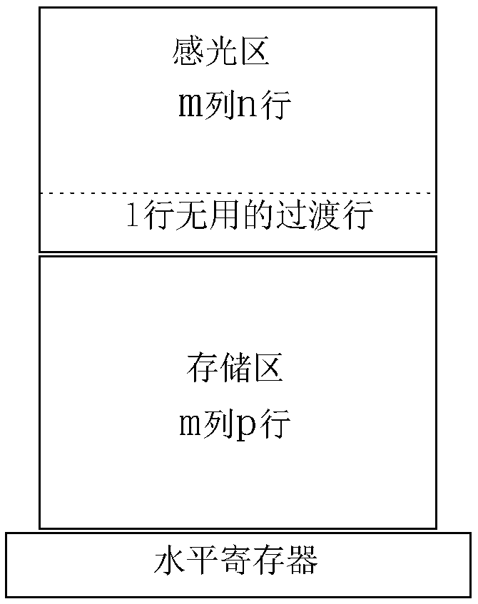
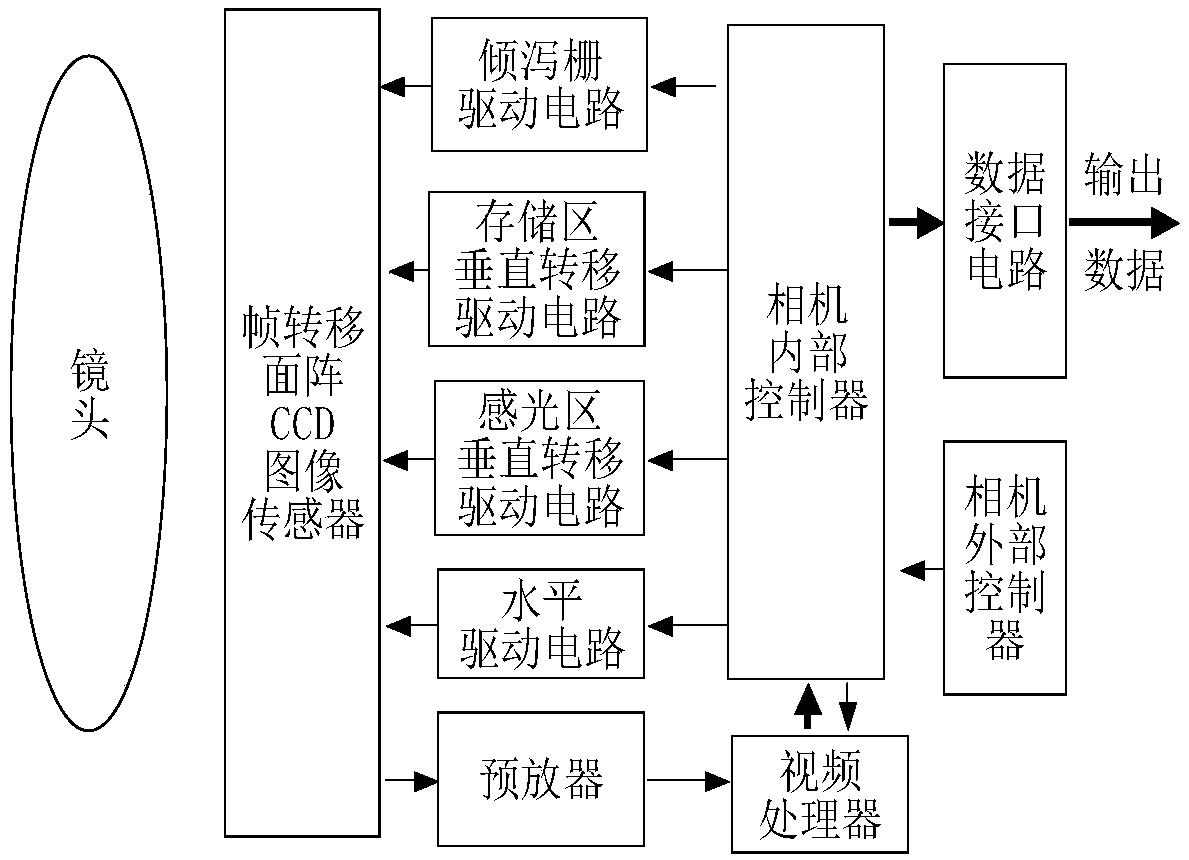
[0028] Specific implementation mode 1. Combination Figure 1 to Figure 4 Describe this embodiment, the exposure time adjustment method for the image motion matching of the earth observation frame transfer area array CCD, such as figure 1 As shown, the number of pixels in the frame transfer area array CCD photosensitive area is set to be m×n, where m is the number of columns, n is the number of rows, and the bottom l of the n rows is a useless transition row; the light-blocking storage area can The number of pixels accommodated is m×p, m is the number of columns, p is the number of rows; m, n, p are all positive integers, l is a positive integer or zero, and p>n>l; frame transfer area array CCD drive block diagram Such as figure 2 As shown, it mainly includes camera external controller, camera internal controller, pouring gate drive circuit (FDG gate drive circuit), storage area vertical transfer drive circuit, photosensitive area vertical transfer drive circuit, horizontal d...


PUM


Abstract

The invention discloses an exposure time adjusting method for earth observation frame transfer area array CCD image motion matching and relates to a frame transfer area array CCD exposure time adjusting method for solving the problem that when the exposure time is too short, the signal to noise ratio is too low, and when the exposure time exceeds one equivalent line period, obvious image blurringoccurs, so that the dynamic transfer function declines along the orbit direction in the existing earth observation imaging application. The method comprises the steps of (1) light-sensitive area useless charge frame transfer phase; (2) controllable-time image motion matching exposure phase; (3) light-sensitive area useful charge frame transfer and original storage area same-line useless charge dumping phase; (4) storage area residual useless charge and light-sensitive area transition-line charge dumping phase; and (5) storage area useful charge frame reading phase. According to the method, theinterval of two times of frame transfer in the light-sensitive area is changed to control the exposure time, a mechanical shutter is not needed, and the original hardware circuit is not modified; andin addition, the image blurring problem under long exposure time is effectively solved.

Description

technical field [0001] The invention relates to an exposure time adjustment method of a frame transfer area array CCD, in particular to an exposure time adjustment method for image motion matching of a frame transfer area array CCD in an earth observation application. Background technique [0002] In the imaging application of earth observation, due to the relative motion of the detector relative to the ground, when the exposure time exceeds one equivalent line period, the image motion exceeds one pixel, and the relative image motion will produce obvious image blur, along the The dynamic transfer function decreases in the rail direction. If the exposure time is lower than an equivalent line period, in order to improve the signal-to-noise ratio, it is usually necessary to increase the aperture of the optical system, increase the volume and weight; if the aperture of the optical system is not increased, the signal-to-noise ratio will be too low, Problem with poor image qualit...

Claims


Application Information

Patent Timeline
IPC IPC(8): H04N5/355H04N5/372H04N5/235
CPCH04N23/73H04N25/57H04N25/71
Inventor 余达刘金国郭永飞司国良陈佳豫梅贵孟祥全
Owner CHANGCHUN INST OF OPTICS FINE MECHANICS & PHYSICS CHINESE ACAD OF SCI
Learn More