
Minimizing circumferential transition lines during container shaping operations

a technology of circumferential transition lines and container shaping, which is applied in the direction of shaping tools, cutting tools, instruments, etc., can solve the problems of difficult or impossible to avoid the formation of visible circumferential transition lines or ripples in the necked-in portion of the resulting container, and the problem is not particularly acute, and the circumferential transition lines tend to be highly noticeabl

Inactive Publication Date: 2009-08-06
NOVELIS INC
View PDF4 Cites 9 Cited by
  • Summary
  • Abstract
  • Description
  • Claims
  • Application Information

AI Technical Summary

Benefits of technology

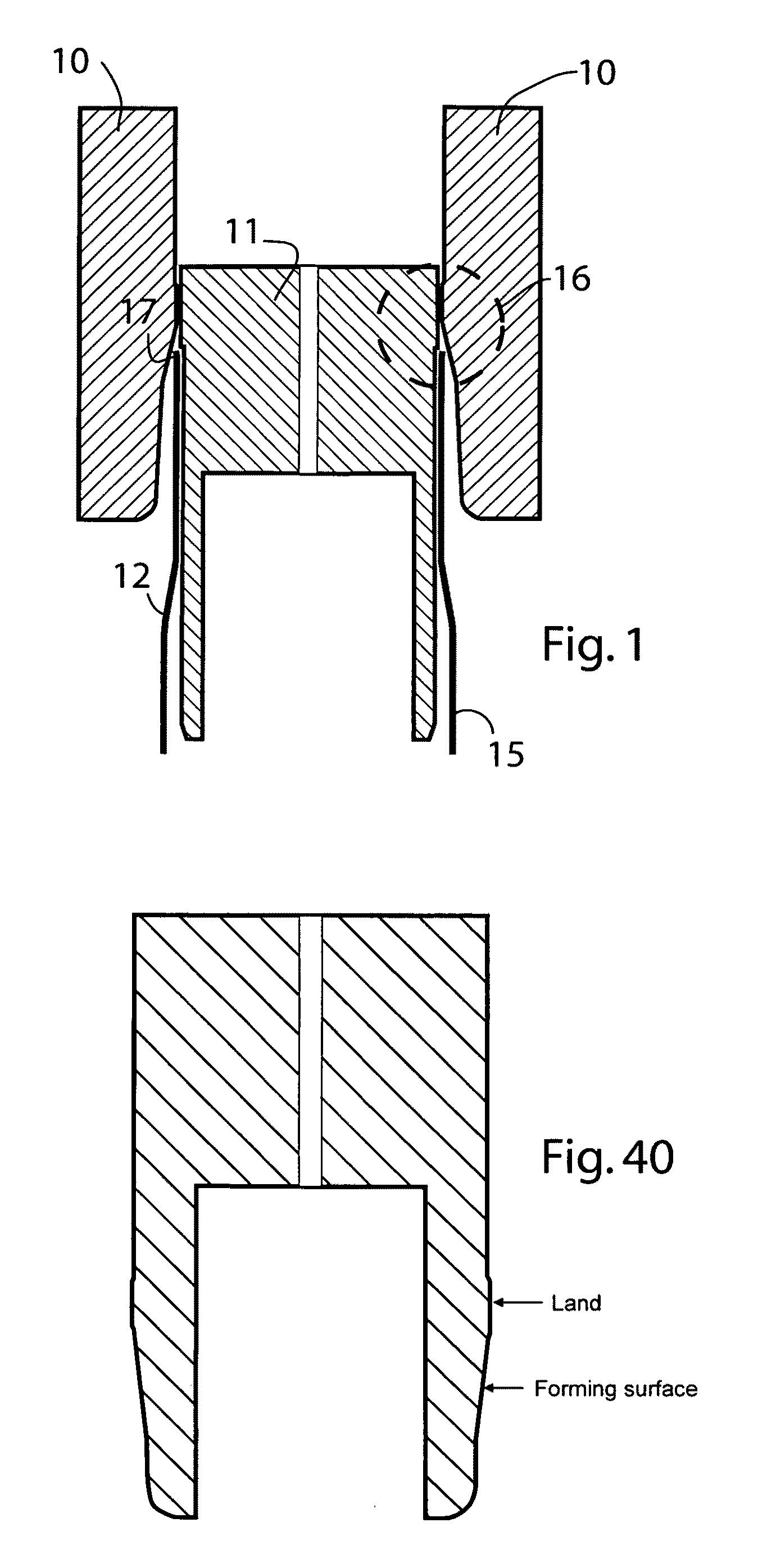
[0015]The redesign of the shaping tools may be made relatively simple (in both the computer models and the actual physical tools). For example, the shaping surfaces below the land may be considered as three segments: an upper curve, a middle segment, and a lower relief curve. These are the segments that may be modified to improve the design. However, to achieve greater shape control, more detailed and accurate tool machining may be preferable.

Problems solved by technology

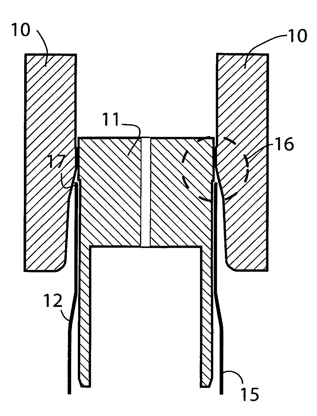
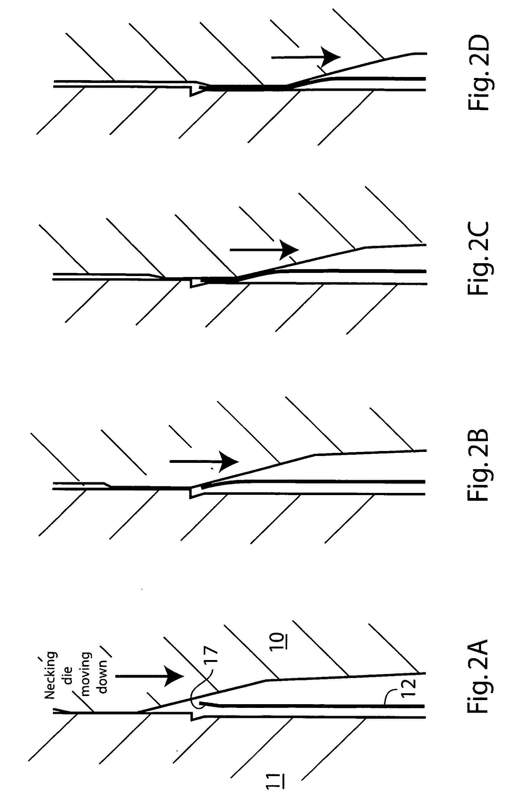
While the die necking process is successful and is used on a large scale for the manufacture of beverage cans and the like, it has proven difficult or impossible to avoid the formation of visible circumferential transition lines or ripples in the necked-in portion of the resulting containers.
In the case of conventional beverage cans, e.g. containers for beer or soft drinks, the problem is not especially acute because of the limited extent of inward necking and because of the necked area is a small portion of the can surface.
The result is that the circumferential transition lines tend to be highly noticeable in the finished Is product and detract considerably from its esthetic appearance.
Furthermore, the lines may make it difficult for the product to accept writing, printing, labels or decoration without distortion or other undesirable visual effects.

Method used


Image

  • Minimizing circumferential transition lines during container shaping operations
  • Minimizing circumferential transition lines during container shaping operations
  • Minimizing circumferential transition lines during container shaping operations

Examples


Embodiment Construction

[0008]One exemplary embodiment of the present invention provides a method of producing a set of tools for use in a shaping operation to shape open ends of an identical set of tubular items made of a deformable metal of known physical properties in a plurality of shaping stages, which method comprises: establishing an optimal profile for the items as a preferred final design profile therefor; providing a first set of tools of progressively different operational size and shape that may be used in succession to shape the items to provide the items with an actual profile at the open ends thereof that approximates the design profile, the use of each tool representing a separate stage of the shaping operation; using the tools to shape one of the items in a multi-stage shaping operation to obtain, at each stage, the item having a first actual shaped profile; for each stage of the shaping operation, measuring a difference produced between the first actual shaped profile of the item and the ...


PUM

PropertyMeasurementUnit
Lengthaaaaaaaaaa
Sizeaaaaaaaaaa
Shapeaaaaaaaaaa

Abstract

The invention provides a method of designing shaping tools for metal containers (such as metal bottles) to minimize the formation of visible transition lines or ripples conventionally produced in such procedures as die necking and outward flaring. The method involves carefully measuring differences between an actual shape produced and a design shape resulting from an original set of shaping tools. The tools are then refined in design to take into account metal spring back and the effect of one shaping stage on the results of previous stages. The redesign goes through several iterations to ensure that each change produces an improvement of the formed container. In this way, the formation of transition lines can be minimized because the actual shape of the container more closely resembles the smooth design shape. Dies designed in this way are then used for commercial shaping operations.

Description

CROSS-REFERENCE TO RELATED APPLICATIONS[0001]This application claims the priority right of prior copending U.S. provisional patent application Ser. No. 61 / 063,187 filed Feb. 1, 2008 by applicants herein.BACKGROUND OF THE INVENTION[0002]I. Field of the Invention[0003]This invention relates to the shaping of open ends of containers made of metal, especially the open ends of containers made of aluminum, steel or other metals of relatively high yield strength. More particularly, the invention relates to such shaping operations carried out with a series of shaping tools, such as necking dies or the like, to shape the containers progressively over a number of stages.[0004]II. Background Art[0005]Metal foodstuff containers, beverage cans, aerosol canisters, and other such containers for consumer or industrial products are often provided with inwardly- or outwardly-flared ends provided for esthetic reasons or for reasons of economy such as metal savings. For example, beverage cans are provi...

Claims


Application Information

Patent Timeline
IPC IPC(8): B21D19/00B21K5/20G06F19/00
CPCB21D19/08B21D51/2615B21D37/20
Inventor HAMSTRA, PETER
Owner NOVELIS INC
Learn More