Network communication system

a communication system and network technology, applied in the field of network communication system, can solve the problems of limiting their effectiveness, unable to acquire information, and the request node cannot acquire the address within the target computer of the application, and achieve the effect of facilitating arp-type communication

Inactive Publication Date: 2003-04-01
SONY CORP
View PDF24 Cites 30 Cited by
  • Summary
  • Abstract
  • Description
  • Claims
  • Application Information

AI Technical Summary

Benefits of technology

It is an object of the present invention to provide a network communication system wherein ARP type communication is facilitated by providing nodes that generate ARP requests with additional information about responding nodes and by allowing for variable length ARP communication packets.
It is a further object of the present invention to provide a network communication system wherein RARP type communication is facilitated by reducing the network's sensitivity to bus resets.
In accordance with the invention, when an ARP type communication session is initiated through request and response packets, the response packet includes an offset address specifying the location of the software application that is the subject of the session. Thereby, allowing session packets subsequent to the response packet to be addressed directly to the application, and allowing those subsequent packets to be of variable size. Furthermore, each network node is assigned a node unique ID for the purpose of providing an unchanging identifier for each node. Thereby, providing an unchanging physical address reference for use in RARP type requests, and allowing RARP type communication to be conducted without interference from network resets.

Problems solved by technology

Both ARP and RARP have drawbacks which limit their effectiveness.
In ARP, a requesting node is limited to acquiring the physical address of a target node, and cannot acquire information that would facilitate communication between itself and the target node.
In particular, the requesting node cannot acquire the address within the target computer of the application which is the subject of the request.
Moreover, the size of the communication packets is limited in ARP, further limiting flexibility.
A drawback of RARP is its sensitivity to bus resets.
When a network bus is reset--such as when the power supply is toggled, or a new device is connected to the network--the physical addresses of the network nodes may change, resulting in the generation of incorrect cross-references by nodes generating RARP responses.
Thereby, resulting in the transmission of incorrect IP addresses to requesting nodes.

Method used


Image

  • Network communication system
  • Network communication system
  • Network communication system

Examples


Embodiment Construction

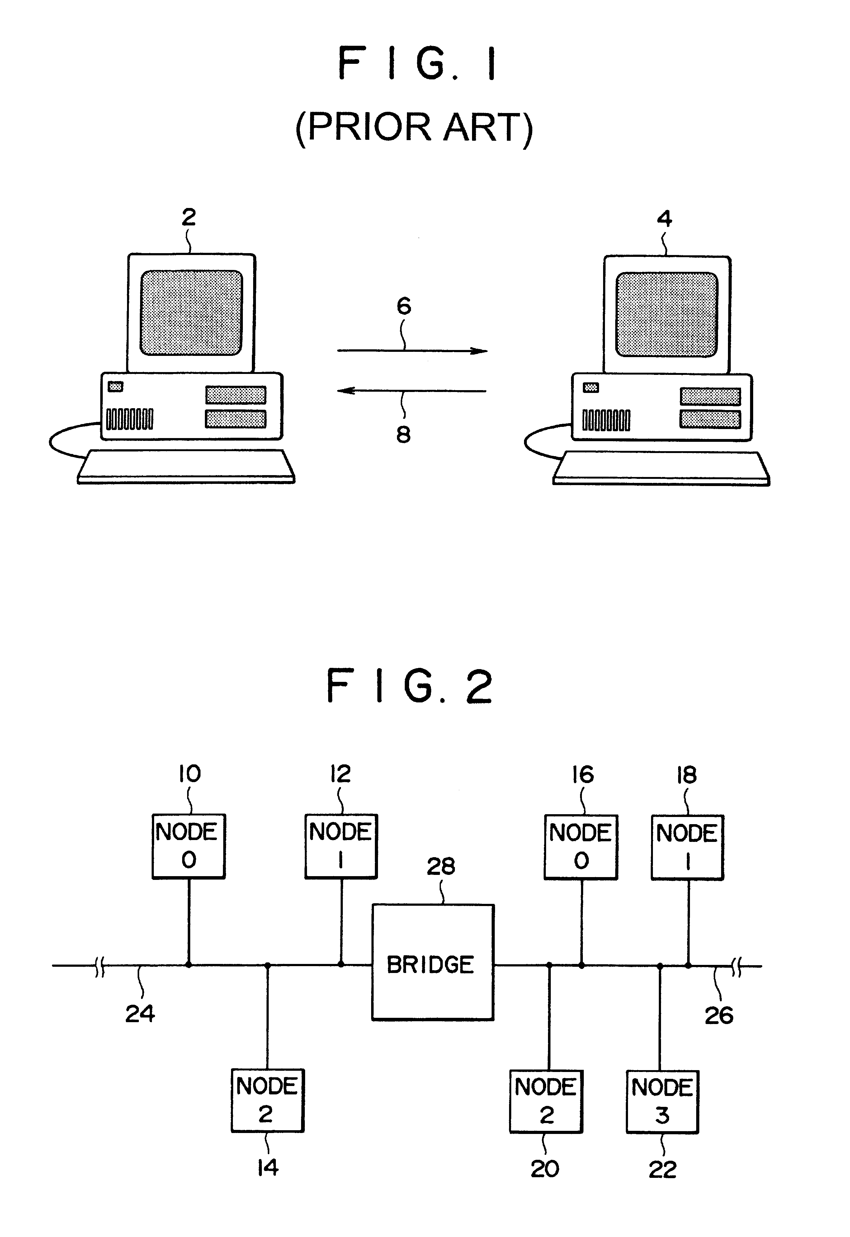
FIG. 2 shows an electronic network in which the present invention may be employed. As can be seen from the figure, the network includes two buses, bus 24 and bus 26, that are coupled together via a bridge 28. Bus 24 is coupled to three nodes, nodes 10, 12 and 14, and bus 26 is coupled to four nodes, nodes 16, 18, 20 and 22. For purposes of illustration, each node of FIG. 2 is considered to be a general purpose computer, buses 24 and 26 are considered to be IEEE-1394 buses, and the bridge is considered to be an IEEE-1394 bridge--although in view of this disclosure it will be apparent that many types of nodes, buses, and bridges are suitable for implementing the invention.

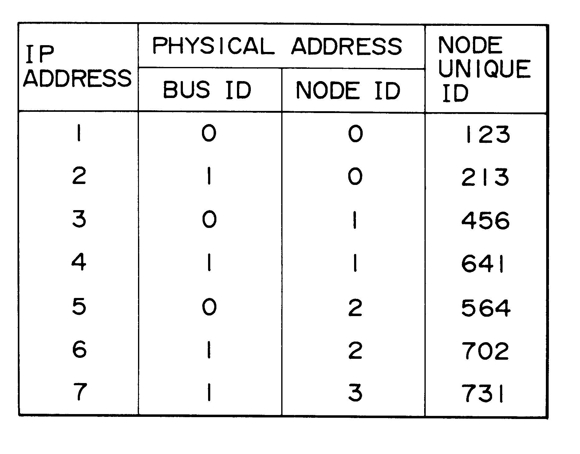
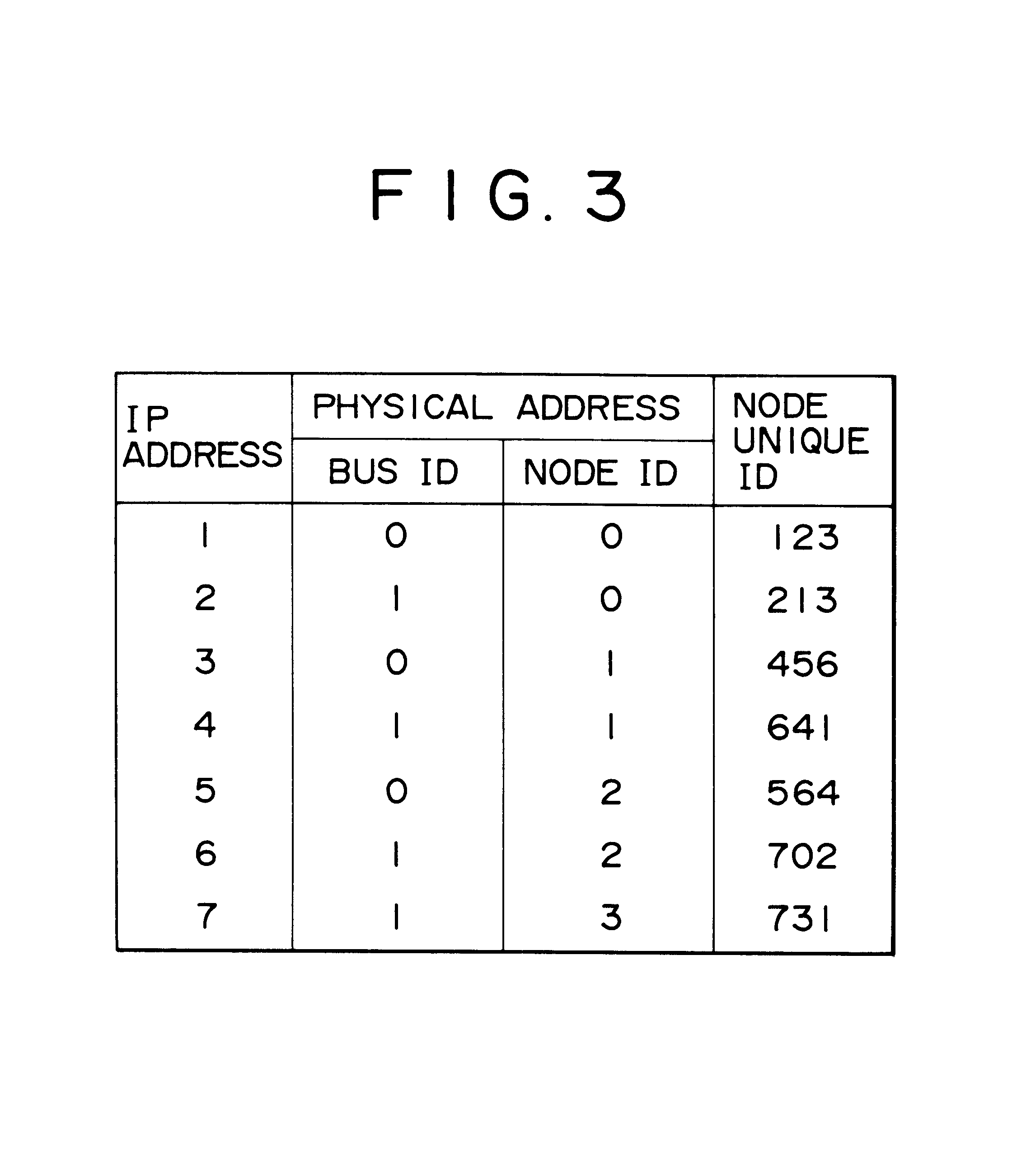
In any event, the buses and nodes of FIG. 2 are assigned identification numbers (IDs). Buses 24 and 26 are referred to as buses "0" and "1", respectively. Nodes 10, 12 and 14 are referred to as nodes "0", "1" and "2", respectively, and nodes 16, 18, 20 and 22 are referred to as nodes "0", "1", "2" and "3", respective...


PUM


Abstract

An electronic network system for implementing ARP (Address Resolution Protocol) and RARP (Reverse Address Resolution Protocol) type communication. ARP type communication is facilitated by including within the ARP response packet an offset address indicating the memory location of the software application that is the subject of the ARP type communication. RARP type communication is facilitated by providing each network node with a network unique ID and using the unique ID when generating RARP requests.

Description

This invention relates to electronic networks, and more particularly to an improved technique for implementing communications between two nodes in an electronic network.There are many well known protocols for implementing electronic communication in a network. Two such protocols are the Address Resolution Protocol (ARP) and the Reverse Address Resolution Protocol (RARP). The ARP and RARP protocols may be used, for example, to implement communications in a network that includes two or more network nodes connected via an electronic bus. An exemplary network is shown in FIG. 1.As can be seen from FIG. 1, transmissions directed from a first general purpose computer 2 to a second general purpose computer 4 are indicated by an arrow 6. Similarly, communications directed from the second computer to the first computer are indicated by an arrow 8. It should be understood that an electronic bus, such as an IEEE-1394 serial bus, interconnects computers 2 and 4, and is used to channel transmiss...

Claims


Application Information

Patent Timeline
Patent Type & Authority Patents(United States)
IPC IPC(8): H04L29/12H04L12/56H04L12/46H04L12/64H04L12/28H04L12/40G06F13/14
CPCH04L12/40091H04L12/4608H04L29/12009H04L61/6009H04L29/12811H04L61/10H04L29/12018H04L61/00H04L61/58H04L12/28
Inventor FUJIMORI, TAKAHIROSATO, MAKOTOTANAKA, TOMOKO
Owner SONY CORP
Why Eureka
Try Eureka