Hydraulic bearing device

a technology of bearings and fluids, applied in the direction of mechanical equipment, metal-working machine components, manufacturing tools, etc., can solve the problems of deteriorating the rigidity, generating great heat due to fluid friction, and deteriorating the bearing performan

Inactive Publication Date: 2003-04-15
TOYODA MASCH WORKS LTD
View PDF11 Cites 34 Cited by
  • Summary
  • Abstract
  • Description
  • Claims
  • Application Information

AI Technical Summary

Problems solved by technology

However, in a case of high rotating speed, a great heat due to fluid friction is generated at the land portion 4.
This is in a vicious circle that causes to deteriorate the performance of the bearing.
However, existence of the drain grooves 7 causes deterioration of the rigidity because the land portion 4 is separated and small.
Moreover, the separated type bearing tends to cause cavitation.

Method used


Image

  • Hydraulic bearing device
  • Hydraulic bearing device
  • Hydraulic bearing device

Examples


first embodiment

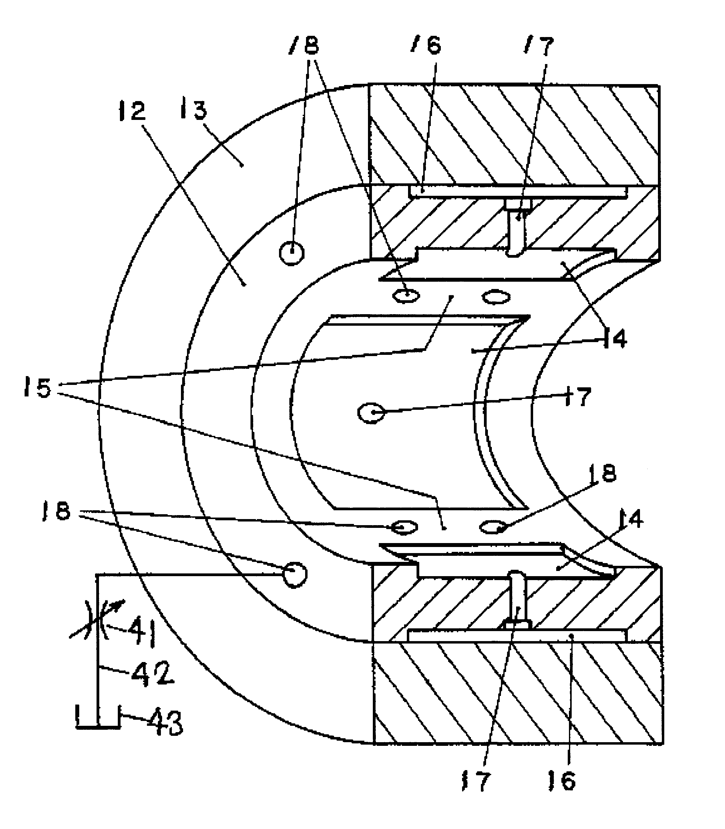
Preferred embodiments of a hydraulic bearing device according to the invention will be described hereinafter with reference to the accompanying drawings. A radial hydraulic bearing device of according to the present invention is employed, for instance, in a wheel spindle apparatus of a grinding machine as illustrated in FIG. 3. The radial hydraulic bearing devices 11 are arranged to support a wheel spindle S at inner surfaces thereof. At one end of the wheel spindle S, a grinding wheel G is attached. A driving belt B is strung between another end of the wheel spindle S and a motor M1, and the wheel spindle S is rotated by the motor M1. Referring to FIG. 4, the radial hydraulic bearing device 11 comprises a ring shape inner sleeve 12 as a bearing metal and a bearing case 13 that the inner sleeve 12 is fixed therein by such as manners of a shrinkage fit or a press fit. Plural hydrostatic pockets 14 are formed on an internal circumference surface of the inner sleeve 12 in a circumferen...

second embodiment

Explanation for the second embodiment that is same constitution as the first embodiment is omitted. Referring to FIG. 11, sensors are prepared for a wheel spindle apparatus of the second embodiment in addition to the constitution of the first embodiment. An encoder 22 is attached on an end face of the wheel spindle S to measure rotating speed of the wheel spindle S. A temperature sensor 23 is attached on a way of the outside drainpipe 42 to measure temperature of the drained lubricant oil. A pressure gauge 24 is attached in the hydrostatic pocket 14 to measure pressure therein. A displacement sensor 25 is disposed between the inner sleeve 12 and wheel spindle S to measure a clearance therebetween. Each of sensors 22, 23, 24 and 25 is connected electrically to a controller 21, and output therefrom is input to the controller 21. The controller 21 is connected electrically to the metering orifice 41 to control opening of the metering orifice 41. Here, all sensors are not required to be...

third embodiment

At third embodiment, the present invention is applied to a thrust hydraulic bearing device. As shown FIG. 17, a flange portion F is formed in a center of a wheel spindle S. A front and a rear thrust bearing metals 31 are arranged to oppose to end surfaces of the flange portion F each other. Each thrust beating metal 31 is ring shape formed a center hole 32 that the wheel spindle S penetrates therein, and fixed on a bearing case C. It is possible to form directly a bearing metal on end surfaces of the bearing case C. As shown FIG. 18, four hydrostatic pockets 34 that are separated ring shape grooves are formed on a surface of the bearing metal 31 which is opposed to the end surface of the flange portion F. Portions of the surface of the bearing metal 31 except the hydrostatic pockets 34 are land portions 35 to generate hydrodynamic pressure. The land portions 35 are consist of an outer land portion 35a, an inner land portions 35b and spoke land portions 35c that are formed between ea...


PUM


Abstract

A hydraulic bearing device that supports a rotating shaft comprises a bearing metal. On a surface of the bearing metal, a hydrostatic pocket and a land portion are formed. The land portion is defined by the hydrostatic pocket and generates hydrodynamic pressure. The hydraulic bearing device further comprises a pressure fluid supplying source and an oil-supplying hole. The oil-supplying hole is opened in the hydrostatic pocket and provides pressure fluid from the pressure fluid supplying source to the hydrostatic pocket. On the land portion, a drain hole that drains the fluid is formed. Since the fluid is drained through the drain hole, thermal expansion of the bearing metal due to heat generation of the fluid is restrained. Moreover, since the drain hole does not separate the land portion, deterioration of bearing rigidity is restrained.

Description

INCORPORATION BY REFERENCEThe entire disclosure of Japanese Patent Applications Nos. 2000-289889 filed on Sep. 25, 2000, 2001-100989 filed on Mar. 30, 2001 and 2001-280095 filed on Sep. 14, 2001 including specification, drawings and abstract is herein by reference in its entirety.1. Field of the InventionThe invention relates to a hydraulic bearing device that supports a rotating shaft or the like.2. Description of the Related ArtFIG. 1 shows three partially developments of inner surfaces of bearing metals which constitute radial hydraulic bearing devices according to the related arts. Plural hydrostatic pockets 1, 2 that are quadrilateral grooves such as shown by FIGS. 1(A) and 1(C) or U-shaped grooves such as shown by FIG. 1(B) are formed on inner surface of the bearing metals along a rotational direction of a rotating shaft. An oil-supplying hole 3 is formed in each hydrostatic pocket. Inner surface of the bearing metal except the hydrostatic pockets are land portions 4 for gener...

Claims


Application Information

Patent Timeline
Patent Type & Authority Patents(United States)
IPC IPC(8): F16C32/06B23Q1/26B23Q1/38F16C41/00
CPCF16C32/0651F16C32/06
Inventor SHIMA, TOSHIHIKO
Owner TOYODA MASCH WORKS LTD
Why Eureka
Try Eureka