Numerically controlling device for electrical discharge machine

a technology of electrical discharge machine and numerical control device, which is applied in the direction of programme control, total factory control, instruments, etc., can solve the problems of imposing a burden on the operator, unable to provide information relating to the measured data of the workpiece and other image plane information, and difficulty in directly measuring the gap

Inactive Publication Date: 2003-04-15
MITSUBISHI ELECTRIC CORP
View PDF23 Cites 18 Cited by
  • Summary
  • Abstract
  • Description
  • Claims
  • Application Information

AI Technical Summary

Benefits of technology

The present invention has been accomplished to solve the above problems. It is an object of the present invention to provide a numerically controlling device for an electrical discharge machine characterized in that: the work condition, mechan

Problems solved by technology

However, since the profile of the workpiece is changed in the working process and further chips are created between the wire electrode and the workpiece in the process of electrical discharge, it is difficult to directly measure the ga

Method used


Image

  • Numerically controlling device for electrical discharge machine
  • Numerically controlling device for electrical discharge machine
  • Numerically controlling device for electrical discharge machine

Examples


embodiment 1

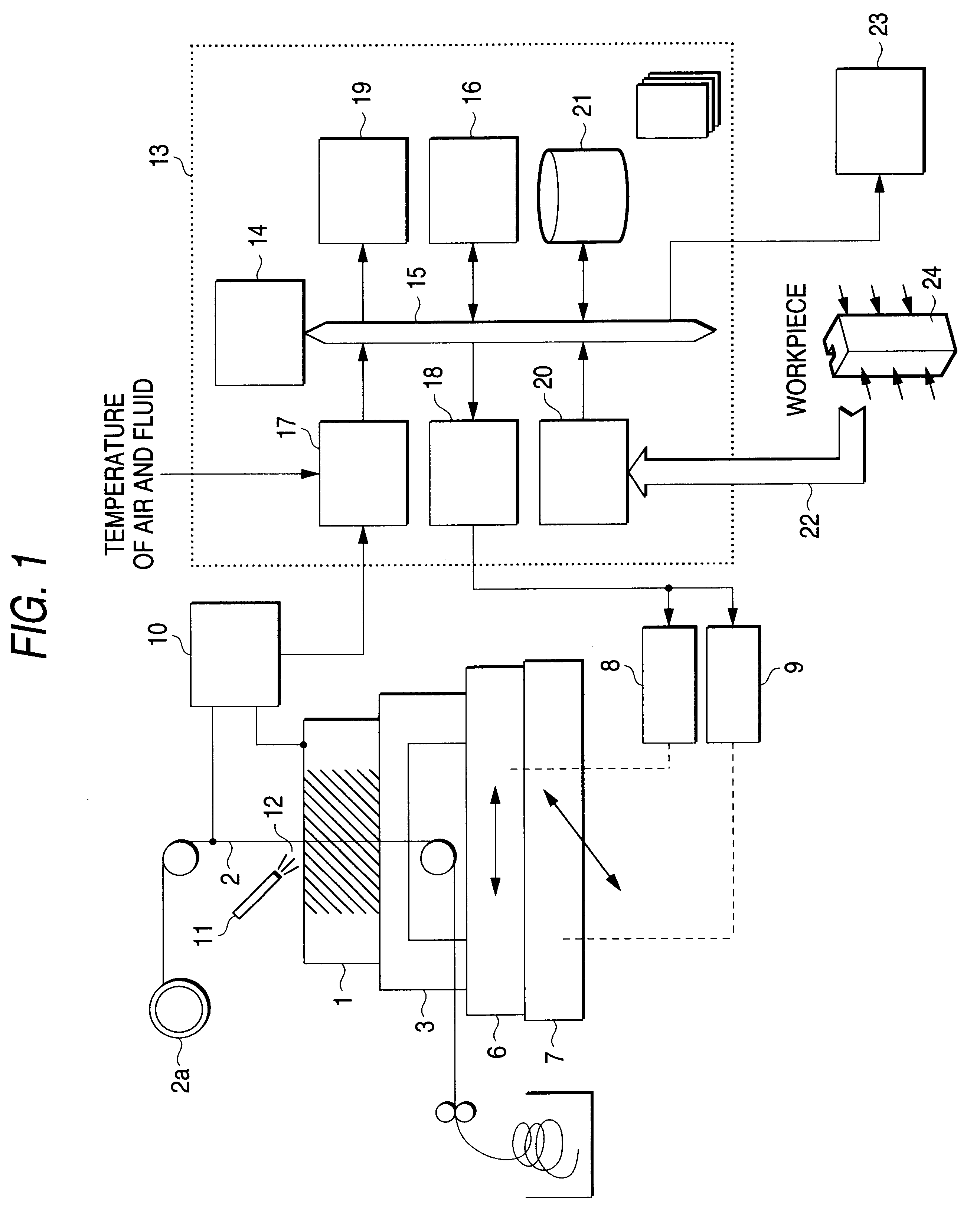
FIG. 1 is a view showing an arrangement of a wire electrical discharge machine into which a numerically controlling device of an embodiment of the present invention is incorporated. In the drawing, reference numeral 1 is a workpiece, reference numeral 2 is a wire electrode, reference numeral 3 is a surface plate onto which the workpiece 1 is fixed, reference numeral 6 is an X-table used for driving the workpiece 1 in the horizontal direction (X-direction), reference numeral 7 is a Y-table used for driving the workpiece 1 in the horizontal direction (Y-direction), reference numeral 8 is an X-axis servo amplifier for controlling a drive motor not shown which drives X-table 6, reference numeral 9 is a Y-axis servo amplifier for controlling a drive motor not shown which drives Y-table 7, reference numeral 12 is a work fluid, reference numeral 11 is a nozzle for injecting the work fluid 12, reference numeral 13 is a numerically controlling device, reference numeral 14 is a CPU of the num...

embodiment 2

FIG. 4 is a view showing an arrangement of a wire electrical discharge machine into which a numerically controlling device of another embodiment of the present invention is incorporated. In the drawing, reference numeral 30 is a computer composed of a main body and a display device, reference numeral 25 is a communication device for transmitting work information of the numerically controlling device 13 to the computer, and reference numeral 31 is a memory device of the computer for recording a work condition, work profile and work monitoring information, which are stored in the computer, in the form of a data base. In this case, the numerically controlling device 13 and the computer 30 are connected with each other by the well known communicating method such as a cable connection of one-on-one, network connection or remote connection via a modem. In this case, other reference numerals of Embodiment 2 are the same as those of Embodiment 1.

Although the structure of the numerically con...


PUM


Abstract

Pieces of information such as work program information, work profile and work condition, which are necessary for an operator to grasp a state of a machine tool, a change in the work voltage necessary for an operator to grasp a state of working a workpiece, pieces of work monitoring information such as a change in the work speed, and measured data of the workpiece are display on a list by a display device of a numerically controlling device for each session of work.

Description

BACKGROUND OF THE INVENTION1. Field of the InventionThe present invention relates to improvements in a numerically controlling device for an electrical discharge machine. More particularly, the present invention relates to improvements in a numerically controlling device for an electrical discharge machine capable of effectively conducting the confirmation of a state of working a workpiece by an operator and also effectively conducting the judgment of a working condition.2. Description of the Related ArtA wire electrical discharge machine is taken up as an example of the electrical discharge machine. The wire electrical discharge machine will be explained as follows. Wire electrical discharge is conducted in such a manner that a wire electrode is arranged being opposed to a workpiece leaving a predetermined interval and a voltage is impressed between the workpiece and the wire electrode under the condition that a working fluid is interposed between the workpiece and the wire electro...

Claims


Application Information

Patent Timeline
IPC IPC(8): G05B19/4062G05B19/406G05B19/418
CPCG05B19/4062G05B19/41875G05B2219/32196G05B2219/31467Y02P90/02
Inventor SATOU, SEIJIINOUE, TORU
Owner MITSUBISHI ELECTRIC CORP
Why Eureka
Try Eureka