Interactive projection system

a projection system and interactive technology, applied in the field of interactive projection systems, can solve the problems of difficult installation and transportation, system furniture is required, and the group usage is not satisfactory,

Inactive Publication Date: 2003-04-29
SONY CORP
View PDF9 Cites 40 Cited by
  • Summary
  • Abstract
  • Description
  • Claims
  • Application Information

AI Technical Summary

Benefits of technology

With this configuration, the at least one support supports the convex mirror so there is no need to mount the convex mirror onto the ceiling above the system. Because the mirror is convex, the image is reflected onto a broader area of the planar surface than if the mirror were flat. Therefore, a large displayed image can be achieved with a relatively small mirror disposed relatively close to the base. The system can be produced in a more compact size.
According to one aspect of the invention, the convex mirror is shaped in a 1 / 4 wedge of a circle am viewed from the image projecting portion. With this configuration, less support is required compared to the case if the convex mirror were shaped like a full circle. When the convex mirror is shaped in a 1 / 4 wedge of a circle as viewed from the image projecting portion, then the camera can be mounted on the base or on the convex mirror. When the camera is mounted on the base, its image-pick-up portion faces the convex mirror so that the camera detects the position indicated by the position indicator as reflected from the convex mirror. This configuration is desirable because even less support is required to support the convex mirror. When the camera is mounted on the convex mirror, its image-pick-up portion faces the displayed image on the planar surface so that the camera detects the position indicated by the position indicator by viewing the displayed image. This configuration is desirable because the camera detects the position indicated by the position indicator directly, thereby avoiding possible distortion by the mirror.
It is desirable that the position indicator include an infrared emitter for emitting infrared light to indicate the position and an infrared lens covering the image-pick-up portion of the camera. In this way, the position indicator can be realized by a simple configuration. Also, the infrared filter filters out light of the projected image, so the camera can detect the position of the position indicator without interference from the light of the projected image.
When plural supports are disposed substantially equidistance from each other external from the convex mirror, the image reflected from the projection path off the convex mirror is blocked to produce shadows in the image displayed on the planar surface. These shadows can be used to enhance functionality of the displayed image. For example, the processor can control the projector to display an opening door in the image when the processor determines that the position indicator is moved from a position on one of the shadows to a position away from the shadow, and control the projector to display objects within the door. With this configuration, the door can serve in the manner of a pop-up menu or tool bar. Also, two adjacent shadows can be used to define a networked area within the displayed image.

Problems solved by technology

However, this type of computer is adapted mainly for personal use and is unsatisfactory for group usage.
However, these projection systems require special furniture or are difficult to install and transport.

Method used


Image

  • Interactive projection system
  • Interactive projection system
  • Interactive projection system

Examples


Embodiment Construction

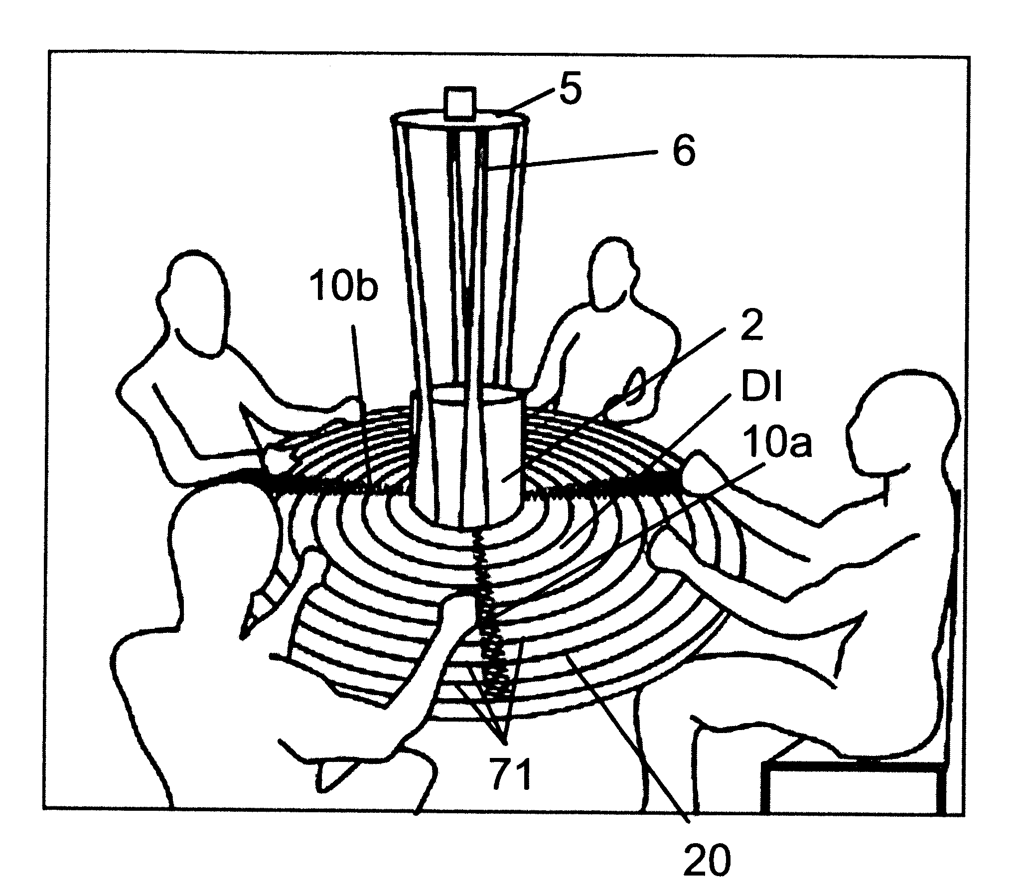
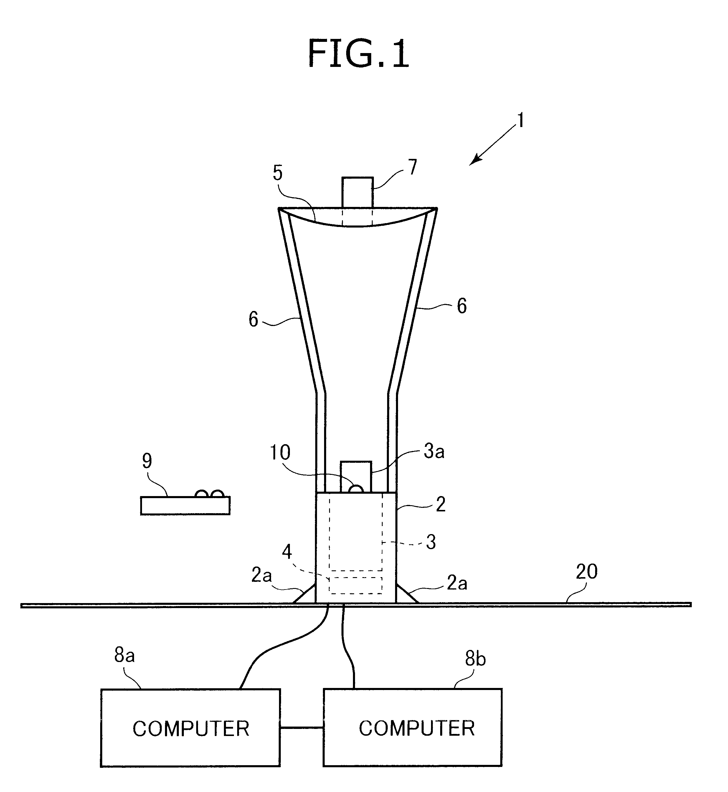
Next, an interactive projection system 1 according to an embodiment of the present invention will be described while referring to the attached drawings. As shown in FIG. 1, the system 1 includes a base 2 housing a projector 3 and a fan 4, a convex mirror 5, supports 6, a camera 7, computers 8a and 8b, an infrared pen 9, and infrared readers 10. The system 1 is used with the base 2 set on a planar surface 20.

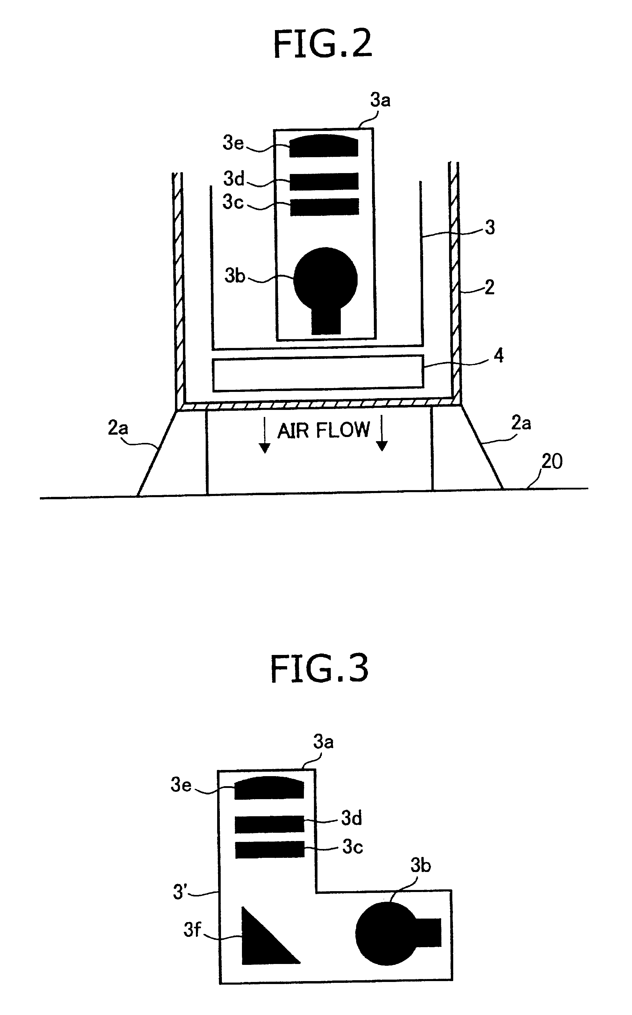
As shown in FIG. 2, the base 2 includes feet 2a to slightly elevate the base 2 above the planar surface 20 to allow the fan 4 to circulate air from the bottom of the base 2. The projector 3 includes an image projecting portion 3a, a lamp 3b, a color wheel 3c, a micro display 3d, and a lens 3e. According to the present embodiment, the optical components of the projector 3 are aligned in a straight line to insure the smallest possible footprint. However, the optical components could be disposed in an L-shaped configuration as shown in FIG. 3.

As shown in FIG. 4, four supports 6 are ...


PUM


Abstract

An interactive projection system for displaying an image on a planar surface includes a base, a projector, a convex mirror, and at least one support. The base is disposed on the planer surface. The projector is housed in the base. The projector has an image projecting portion that projects an image along a projection path away from the projector. The at least one support is connected to the base and supports the convex mirror at a position along the projection path so as to face the image projecting portion of the projector and the planar surface.

Description

1. Field of the InventionThe present invention relates to computer displays, interactive displays, input and output methods for computers, and particularly to interactive projection systems.2. Description of the Related ArtComputers typically include a display for displaying information, and a keyboard and a mouse to enable a user to interact with the computer based on the displayed information. However, this type of computer is adapted mainly for personal use and is unsatisfactory for group usage.Recently, interactive projection systems have been developed for projecting images on a table top for meetings, presentations, and the like. One conventional projection system includes a projector disposed underneath a transparent table top. The projector projects images onto the under surface or the table top so that the images are visible to people sitting around the table. Another conventional system has a projector that projects an image onto a mirror that is mounted on the ceiling abo...

Claims


Application Information

Patent Timeline
Patent Type & Authority Patents(United States)
IPC IPC(8): G06F3/033G03B21/28G06F3/042
CPCG06F3/0425G03B21/28
Inventor SCIAMMARELLA, EDUARDO A.OBA, HARUO
Owner SONY CORP
Why Eureka
Try Eureka