Method and printer for applying an ink image to a receiving material

a technology for receiving materials and printers, applied in printing, instruments, printing, etc., can solve the problems of introducing positioning errors, requiring calibration steps, and introducing positioning errors, so as to improve accuracy, increase contrast, and facilitate and more accurate detection

Inactive Publication Date: 2005-03-17
OCE TECH
View PDF8 Cites 31 Cited by
  • Summary
  • Abstract
  • Description
  • Claims
  • Application Information

AI Technical Summary

Benefits of technology

[0031] In another embodiment of the present invention, the ink image is printed in two or more passes of the carriage over the strip of receiving material, wherein the receiving material is stepwise advanced in the direction of advance, after each pass. Printers wherein an ink image to a strip of receiving material is printed in a number of passes are referred to as multipass printers. In such a multipass printer the total amount of needed ink on a certain position in the ink image is printed in n passes (n>2). As a consequence of this, the amount of ink increases in n steps in the direction of advance of the receiving material. Such a stepwise increase of the amount of ink, referred to as multipass edge, extends substantially perpendicular to the direction of advance and can be used to measure the stepwise advance of the receiving material of the previous (n−1) steps. An advantage of this embodiment is, that no reference pattern is required in the margin of the receiving material. Moreover, the reference pattern is dispersed over the width of the receiving material and is automatically generated by the multipass printing process. Thus, the introduction of the reference pattern in the ink image is not necessary.
[0032] In one embodiment, the print head comprises a first printing device for printing a first color of the ink image and a second printing device for printing a second color of the ink image, wherein the second color is different from the first color, which first and second printing devices are mounted adjacent to each other, wherein the first printing device is displaced in the direction of advance with respect to the second printing device. The method of the present invention further comprises the steps of moving the carriage over the strip of receiving material for a first pass, wherein only the first printing device prints on at least a part of the strip of receiving material, advancing the receiving material in the direction of advance over at least one step, and moving the carriage over the strip of receiving material for a second pass, wherein the second printing device prints on said part of the strip of receiving material. As a consequence of this, not only the amount of ink increases in steps in the direction of advance of the receiving material, but also the color changes in steps (here in at least two steps) in the direction of advance. This color change yields a multipass edge with an increased contrast, wherein the position of this multipass edge is easier and more accurate detectable.
[0033] In another embodiment, the printer comprises processing means, wherein the method comprises the step of processing ink image data by said processing means for introducing the reference pattern in a first part of the ink image and printing the reference pattern during the first pass, and for introducing a compensation pattern in a second part of the ink image and printing the compensation pattern during the second or a subsequent pass, wherein said compensation pattern neutralizes said reference pattern. An advantage of this method is that not only the multipass edges are available, but also an additional reference pattern is visible and can be used for further improving the accuracy with which the stepwise advancing of the receiving material can be determined.
[0034] In the case of a multipass printer which requires n passes over a strip of receiving material to complete the printing of the ink image on said strip of receiving material, reference patterns can be introduced to the first (n−1) passes. At the last pass (n) a correction is made to neutralize the introduced reference patterns, so that the use of the reference patterns will not be visible in the final print. The reference patterns will however be visible for the camera in the (n−1) previous passes. In this way, not only the multipass edges can be used to measure the stepwise advancing of the receiving material, but also all the positions of the reference patterns, making the measurement more accurate because more measurements can be made.

Problems solved by technology

A known problem with swath-type printers is the accurate positioning of the stepwise advancing of the receiving material effected by the transporting element.
A disadvantage of the known method is that after each advancing step of the receiving material, a calibration step is required for positioning the receiving material before the next successive swath can be printed.
A further disadvantage is that the advancement of the receiving material is relatively slow in order to obtain the same value of the difference signal and not to overshoot this position.
Another disadvantage is, that after the accurate advancement of the receiving material until the same value of the difference signal is obtained, the receiving material is subsequently advanced at a predetermined amount to position the receiving material for the next successive swath to be printed.
This subsequent advancement over said predetermined amount may introduce positioning errors.

Method used


Image

  • Method and printer for applying an ink image to a receiving material
  • Method and printer for applying an ink image to a receiving material
  • Method and printer for applying an ink image to a receiving material

Examples


Embodiment Construction

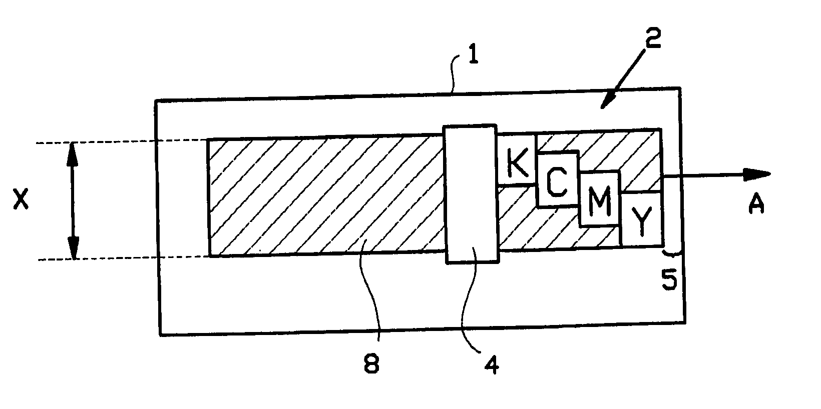
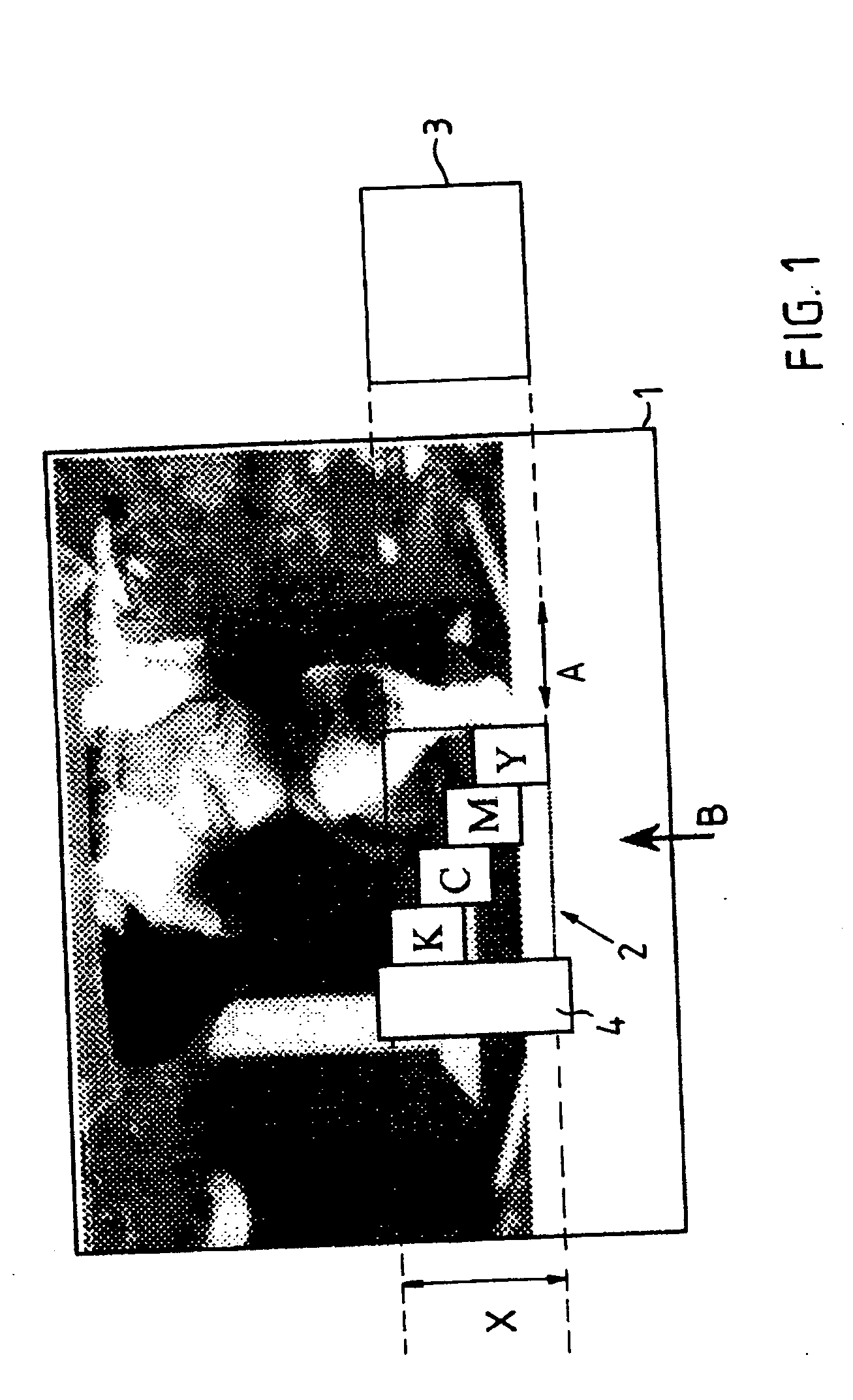
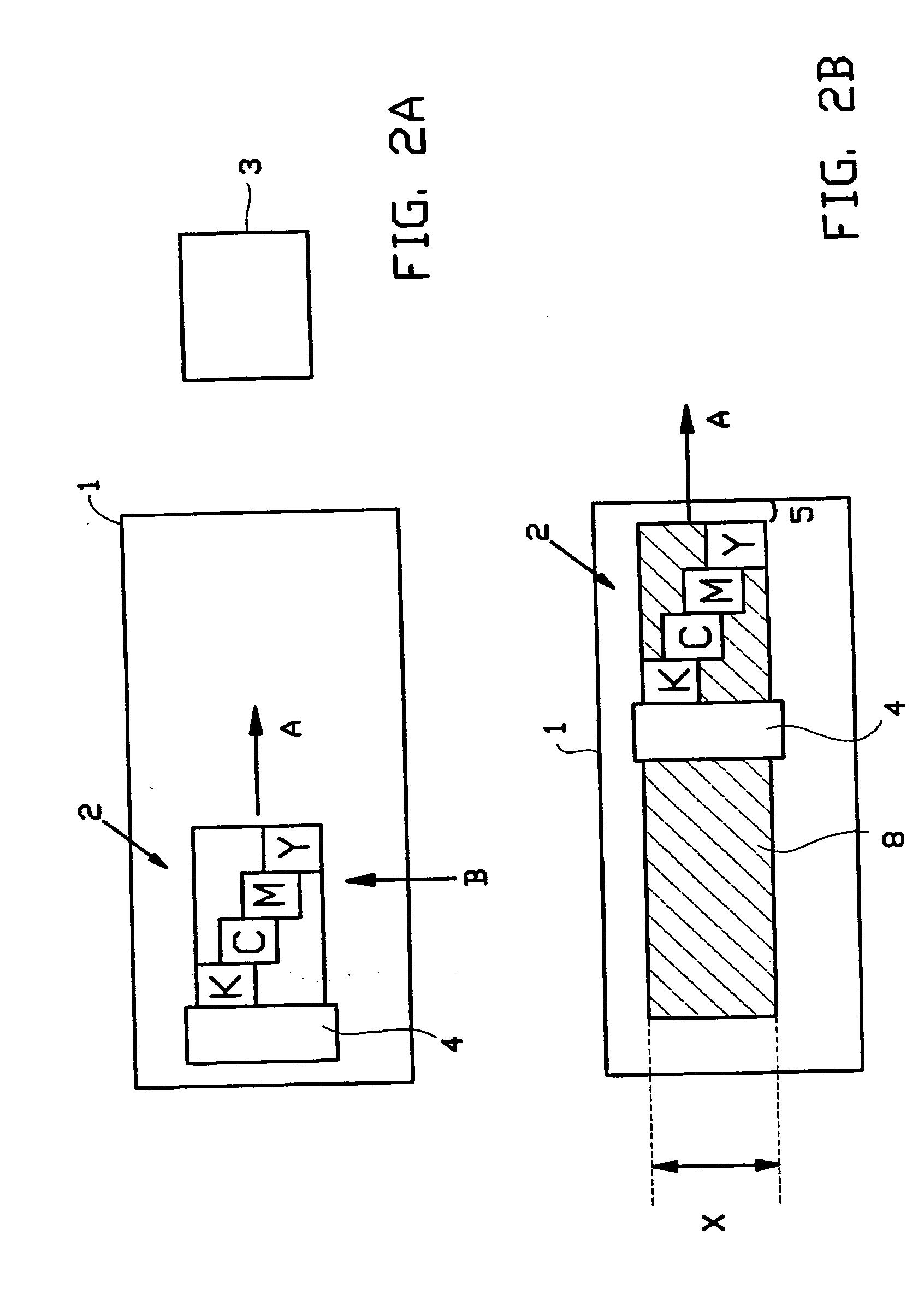
[0063] A simplified printer situation is presented in FIG. 1. FIG. 1 shows a top view of a receiving material 1 (in this case paper) onto which an ink image is printed. For printing the ink image, the printer utilizes a carriage 2 which is movable along a carriage scan-axis A for applying the ink image to the paper 1. The paper 1 is stepwise advanced in the direction of advance B, which extends in the direction substantially orthogonal to the carriage scan-axis A. During the printing of an image the carriage 2 is driven back and forth along the scan-axis A to print the successive swaths with the print head. When not in use the print head is stored in a capping station 3 which is situated at one end of the scan path of the carriage 2. The carriage 2 is provided with a print head comprising four printing devices Y, M, C and K which are displaced with respect to each other in the direction of advance B. The first printing device that prints on a strip of paper is the printing device Y ...


PUM


Abstract

A method for applying an ink image to a receiving material using a printer containing a carriage holding a print head, the carriage being moveable along a carriage scan-axis for applying the ink image to a strip of receiving material, transporting means for stepwise advancing the receiving material in a direction of advance, which extends to a direction substantially orthogonal to the carriage scan-axis, and a camera mounted on the carriage adjacent to the print head for detecting a reference pattern, wherein the camera is arranged for imaging an area which extends in the direction of advance, said method including the steps of: moving the carriage for printing a swath in a direction wherein the camera is positioned upstream to the print head, detecting the position of a reference pattern on the receiving material relative to the carriage, determining deviations in said position from a desired position, and adjusting the position of the receiving material in the direction of advance for at least partially correcting for the deviations during the movement of the carriage.

Description

[0001] This non-provisional application claims priority under 35 U.S.C. 119(a) on Patent Application No. 03077931.8 filed in Europe on Sep. 16, 2003, which is herein incorporated by reference. BACKGROUND OF THE INVENTION [0002] The present invention relates to a method for applying an ink image to a receiving material. In particular the present invention relates to a printing method used in a swath-type printer. The present invention further relates to a printer for applying an ink image to a receiving material. [0003] Swath-type printers are well known in the art. Typically such printers include a carriage for holding a print head, which carriage is moveable along a carriage scan-axis for applying an ink image to a strip of receiving material. The receiving material, such as a paper sheet, is stepwise advanced in the direction of advance, which extends in a direction substantially orthogonal to the carriage scan-axis. During the printing of an image, the carriage is driven back and...

Claims


Application Information

Patent Timeline
Patent Type & Authority Applications(United States)
IPC IPC(8): B41J2/01B41J2/51B41J11/42B41J11/46B41J13/00B41J29/46B41J29/50G03B29/00
CPCB41J13/0027B41J11/46
Inventor DE GRIJS, EDUARD T.H.
Owner OCE TECH
Why Eureka
Try Eureka