Cooling system for watercraft

a technology for watercraft and cooling system, which is applied in the direction of steam power plants, marine propulsion, vessel construction, etc., can solve the problems of not being able to complement an automotive engine selected for other performance or size characteristics, the watercraft engine compartment cannot accommodate the stock exhaust manifold of the automotive engine, and the typical automotive engine is often not properly proportioned or configured to fit within a confined engine compartmen

Inactive Publication Date: 2003-04-29
YAMAHA MOTOR CO LTD
View PDF10 Cites 16 Cited by
  • Summary
  • Abstract
  • Description
  • Claims
  • Application Information

AI Technical Summary

Problems solved by technology

A typical automotive engine, however, is often not properly proportioned or configured to fit within a confined engine compartment of such watercraft.
For instance, the watercraft engine compartment can not accommodate the stock exhaust manifold of the automotive engine.
Additionally, due to the unique cooling and exhaust systems required for use in marine environments, the stock watercraft manifold can not complement an automotive engine selected for other performance or size characteristics.
Preferably, the engine and exhaust cooling systems are supplied with water from a pressure chamber within the jet pump unit of the watercraft, thereby rendering a further cooling water pump unnecessary.

Method used


Image

  • Cooling system for watercraft
  • Cooling system for watercraft
  • Cooling system for watercraft

Examples


Embodiment Construction

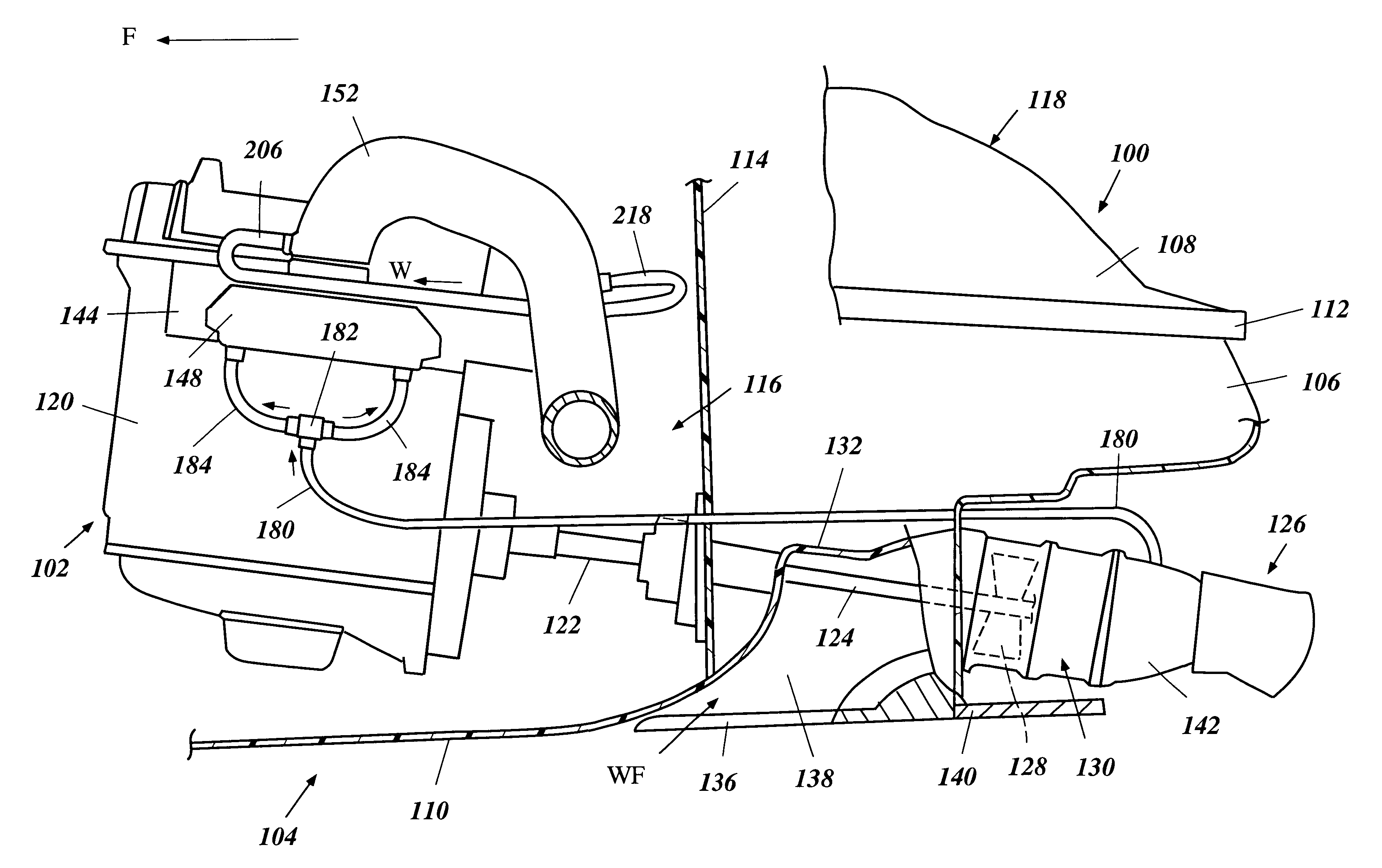
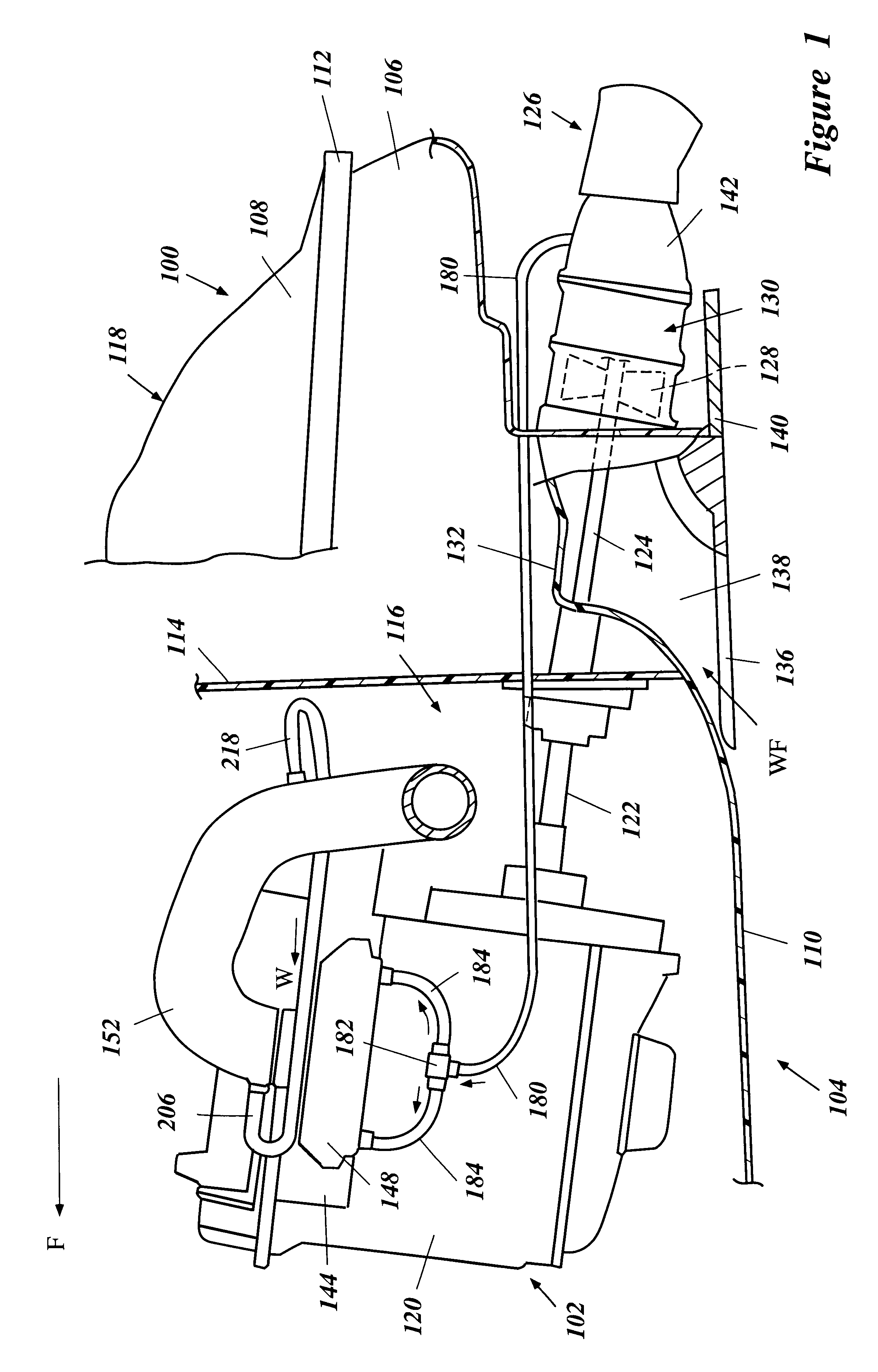
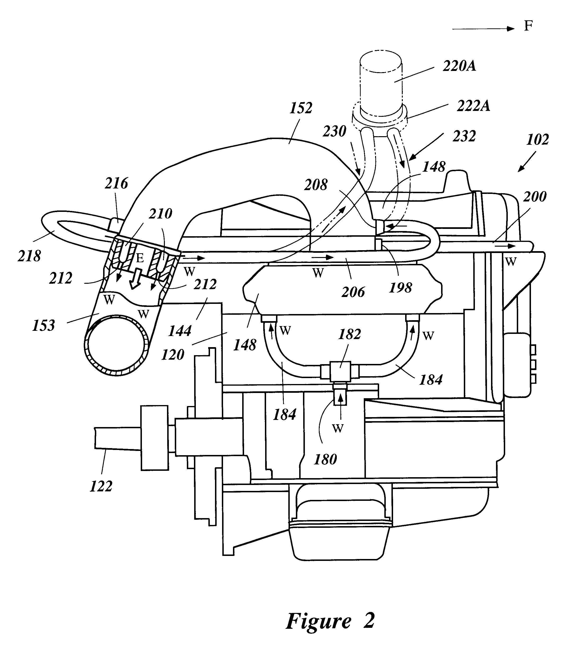
With reference to FIG. 1, a portion of a small watercraft, indicated generally by the reference numeral 100, is partially illustrated in cross-section. The watercraft 100 is powered in a known manner by an engine 102 having features, aspects and advantages in accordance with the present invention. The engine 102 is better shown in FIGS. 2-6. While the present invention will be described with reference to the illustrated arrangements that feature certain types of engines, the present invention also can be used with other engine configurations. For instance, but without limitation, an exhaust system can extend from either side of the engine (compare FIGS. 1 and 2).

With continued reference to FIG. 1, the watercraft 100 has a hull, indicated generally by the reference numeral 104. The hull 104 can be made of any suitable material; however, a presently preferred construction utilizes molded fiberglass reinforced resin. The hull 104 generally has a lower portion 106 and an upper portion 1...


PUM


Abstract

An engine for a watercraft has a coupling plate interposed between a cylinder block and an exhaust manifold. The coupling plate comprises exhaust passages that complement the shapes of cylinder exhaust discharge ports and the exhaust manifold inlet ports. The coupling plate also includes a water jacket for use with a water cooling system. The cooling system can receive coolant from a pressure chamber within a jet pump unit of the watercraft. The cooling system also can include a lubricant cooler that receives coolant from an engine cooling jacket, an exhaust system cooling jacket or another cooling jacket.

Description

1. Field of the InventionThe present invention generally relates to engines used in watercraft. More particularly, the present invention relates to cooling systems for engines adapted for use in watercraft.2. Description of the Related ArtWatercraft can be powered by various engine configurations. Some watercraft are powered by outboard motors that are attached to the aft end of the watercraft and that contain internal combustion engines while other watercraft are powered by inboard engines contained within engine compartments formed within the body of the watercraft. The engine compartments are desirably configured as compactly as possible because they necessarily encroach upon the limited floor space of the watercraft.Until recently, the majority of the inboard engines utilized in smaller sport watercraft have been specially designed for use in such watercraft. The engines are compactly constructed and specially designed for use in small enclosed spaces. For instance, the engines ...

Claims


Application Information

Patent Timeline
Patent Type & Authority Patents(United States)
IPC IPC(8): F01N3/04F01N7/00F02B61/00F02B61/04B63H11/00B63H11/08F01N13/00
CPCB63H21/383F01N3/046F02B61/045F01N13/004B63H11/08Y02T10/20F01N2590/02Y02T10/12
Inventor NANAMI, MASAYOSHI
Owner YAMAHA MOTOR CO LTD
Why Eureka
Try Eureka