Flow control device, introducer and method of implanting

a flow control device and introducer technology, applied in the field of medical implants, can solve the problems of clogging of implants, affecting the safety of patients, and prior implants at times requiring insertion operations that are complicated, costly, and time-consuming, and achieves the effect of simple and efficient procedures

Inactive Publication Date: 2003-05-06
MARY C WERNER
View PDF128 Cites 203 Cited by
  • Summary
  • Abstract
  • Description
  • Claims
  • Application Information

AI Technical Summary

Benefits of technology

One object of the invention is to provide a flow regulating implant and an associated delivery device that enable the implant to be inserted in a relatively simple and efficient procedure.
The retention projection may be made, for example, of an elastic material, so that it is able to be flexed inward against the tube of the implant during penetration through the tissue. Alternatively, the retention projection may be designed to lie initially relatively flat against the tube for easier penetration and to prevent tearing of the tissue, with a mechanism for extending the retention projection outwardly when the implant is implanted.
Another object of the invention is to provide a simple and efficient method of manufacturing a flow regulating implant. In a method for manufacturing an implant according to an embodiment of the invention, the device may be molded out of a suitable material, for example, silicone. To provide the tube passage of the implant, a thin wire may be used during the molding process. The implant alternatively may be constructed out of stainless steel or any other suitable material.

Problems solved by technology

Several disadvantages have at times been associated with prior implants.
For example, implants using valve mechanisms to regulate fluid flow have risked malfunction due to defects in and / or failure of such valve mechanisms.
Depending on such factors as the site of implantation, some implants have tended to clog while in use due to tissue covering the inlet end or the outlet end of the drainage tube.
In addition, prior implants at times have required insertion operations that are complicated, costly, and time-consuming, for example requiring suturing of the implant once it is in place.

Method used


Image

  • Flow control device, introducer and method of implanting
  • Flow control device, introducer and method of implanting
  • Flow control device, introducer and method of implanting

Examples


first embodiment

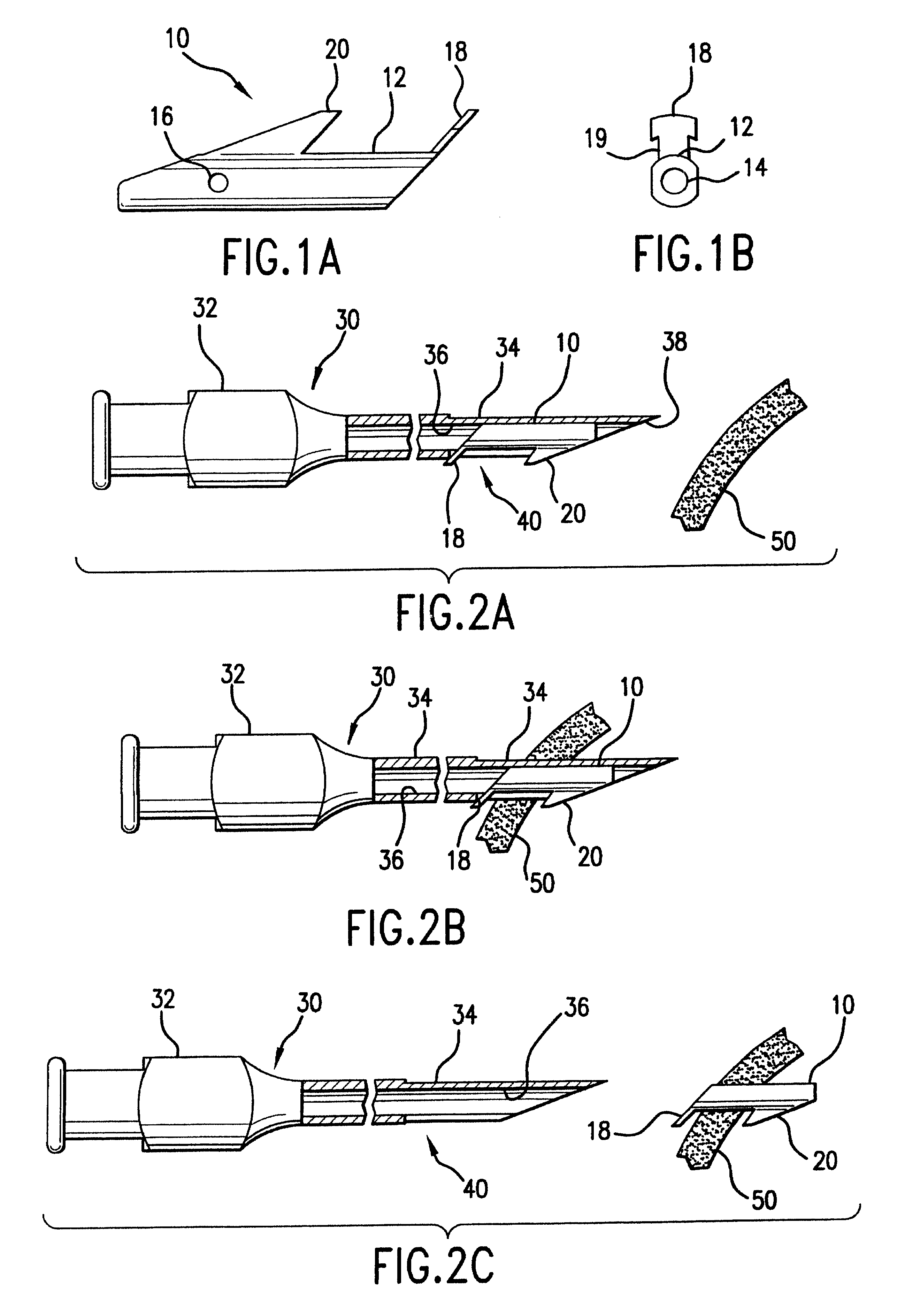
FIGS. 1A and 1B show a side view and end view, respectively, of a drainage implant 10 in accordance with the invention. The implant 10 has a tube 12 having a tube passage 14 for permitting fluid flow between an inlet end of the implant and an outlet end of the implant. One or more side holes 16 may be provided around the circumference of the tube 12 near the inlet end, allowing access for fluid flow into the tube passage 14.

The implant 10 has an outer flange 18 at the outlet end and a retention projection 20 near the inlet end. The plane of the outer flange 18 may form an angle with the tube 12, with the angle selected to correspond to the angle between the surface of the tissue into which the implant 10 is to be inserted and the axis of insertion of the tube 12 of the implant 10.

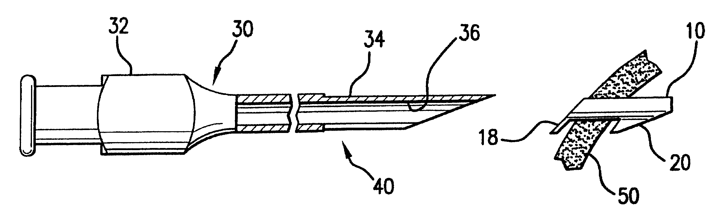
FIGS. 2A through 2C illustrate an introducer or delivery device 30 for implanting the implant 10 and the method of implanting the implant 10 with that delivery device 30. The delivery device 30 has handle 3...

second embodiment

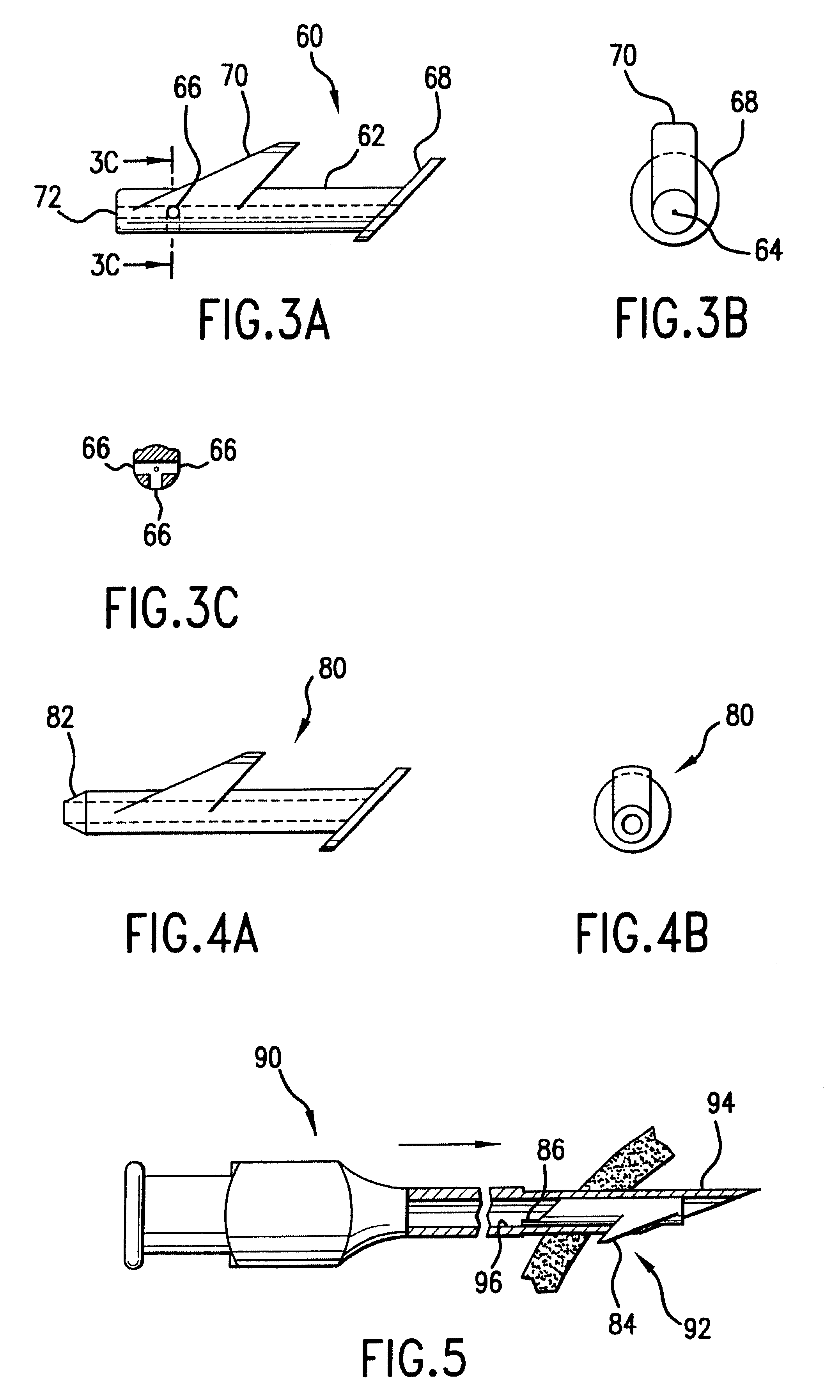
FIGS. 3A, 3B and 3C show a side view, end view, and cross-section, respectively, of a drainage implant 60 in accordance with the invention. Like the implant 10 shown in FIGS. 1A and 1B, the implant 60 in FIGS. 3A, 3B, and 3C has a tube 62 having a tube passage 64 and side holes 66 opening into the tube passage 64. The implant 60 also has an outer flange 68 at the outlet end and a retention projection 70 near the inlet end. In this case, the outer flange 68 projects beyond the outer surface of the tube 62 in all directions around the circumference of the tube 62.

third embodiment

FIGS. 4A and 4B show a side view and end view, respectively, of a drainage implant 80, similar to the implant 60 shown in FIGS. 3A, 3B, and 3C. The tip 82 of the implant 80 is conical, in contrast to the blunt tip 72 of the implant 60.

In an alternative construction, the implant may be made with a closed end with a slit in it. Fluid can only pass through the device when the pressure rises sufficiently to open the slit. Alternatively, a different portion along the length of the tube passage may be provided with such a construction.

FIG. 5 illustrates an alternative embodiment of a delivery device 90 in accordance with the invention. In this embodiment, the opening 92 allows only the retention projection 84 of the implant to protrude beyond the wall of the tube 94 of the delivery device. The outer flange 86 is accommodated within the central bore 96 of the delivery device 90. In this embodiment, the outer flange 86 must be folded or bent to be accommodated within the central bore 96 of ...


PUM

PropertyMeasurementUnit
diameteraaaaaaaaaa
diameteraaaaaaaaaa
intraocular pressureaaaaaaaaaa

Abstract

An implant having a tube for permitting fluid flow has an outer flange at the outlet end and a retention projection near the inlet end. A delivery device for implanting the implant has a central bore for accommodating the implant during the implantation procedure. When the implant is loaded in the delivery device, the retention projection of the implant protrudes beyond the outside surface of the delivery device. After the delivery device and implant have penetrated the tissue through which drainage is desired, and the retention projection has fully penetrated through the tissue, the delivery device is withdrawn. The retention projection acts as a hook engaging the inside surface of the tissue, causing the implant to stay implanted in the tissue. An implant may also be provided with a mechanism for temporary occlusion, in whole or in part, of the flow passage. Thus, the tube passage may be filled, partially or wholly, with absorbable material and / or a plurality of withdrawable or advanceable flow controlling strands.

Description

FIELD OF THE INVENTIONThe invention relates generally to medical implants used to regulate the flow of fluids within the body. The invention may be applied, for example, to ophthalmic implants for treatment of glaucoma. The invention also relates to delivery devices for implanting such implants, to methods of implanting such implants, and to methods of manufacturing such implants.BACKGROUND OF THE INVENTIONMedical implants used to regulate the flow of fluids within the human body are known and used. One application for the use of such implants is in the treatment of glaucoma. Typical ophthalmic implants utilize drainage tubes for the release of aqueous humor from the eye to relieve the intraocular pressure (IOP).Several disadvantages have at times been associated with prior implants. For example, implants using valve mechanisms to regulate fluid flow have risked malfunction due to defects in and / or failure of such valve mechanisms. Depending on such factors as the site of implantati...

Claims


Application Information

Patent Timeline
Patent Type & Authority Patents(United States)
IPC IPC(8): A61F9/007A61F2/00A61F2/02
CPCA61F9/00781A61F2250/0069A61F2210/0004
Inventor YARON, IRAYARDEN, ORIT
Owner MARY C WERNER
Why Eureka
Try Eureka