Method for operating a gas turbine plant with gaseous fuel

a gas turbine and gaseous fuel technology, which is applied in the direction of turbine/propulsion fuel heating, machines/engines, mechanical equipment, etc., can solve the problems of increased firing power, gas line pressure loss, and variations in gas quality, so as to reduce the temperature of the fuel, reduce the pressure loss in the fuel system, and minimize the effect of throughflow

Active Publication Date: 2021-08-12
SIEMENS ENERGY GLOBAL GMBH & CO KG
View PDF0 Cites 0 Cited by
  • Summary
  • Abstract
  • Description
  • Claims
  • Application Information

AI Technical Summary

Benefits of technology

[0012]The present position of the valve is known at all times since the mass flow in the gas line, a part of which is the valve, is known. In particular, the position of the valve is set in a manner dependent on the mass flow. The latter is measured directly or determined indirectly on the basis of various parameters. If the valve is in the critical opening position but the pressure in the gas line is insufficient, in particular since the requirements for the pressure increase or the pressure in the line drops, the lowering of the gas temperature is to be initiated as the first measure for maintaining the target power. The temperature of the fuel has a significant effect on the pressure in the gas line. The reduction of the gas temperature results in the density of the gas increasing, which leads to lower pressure losses in the fuel system.
[0013]Preferably, the critical opening position of the valve is in the range above 70% of the maximum opening position. The maximum opening position is the position in which the mass flow in the gas line is at its greatest. The decisive critical opening position of the valve is thus not necessarily the maximum open position of the valve (although it is also possible for the critical opening position to be defined by the maximum opening position too), but rather a position with slightly minimized throughflow. The advantage here is that reaction to rapid short-term changes to the operating parameters, such as for example fluctuations in the quality of the fuel, is possible by way of further opening of the valve. The critical opening position may also be adapted to the operating conditions retrospectively, by being changed during operation.
[0014]The reduction of the temperature of the fuel may be realized via active cooling measures. Preferably, however, the gas turbine plant has a preheating system for the fuel, and the temperature of the fuel in the gas line is reduced by reduction of the heat in the preheating system that is supplied to the fuel. This is a particularly simple and efficient procedure for lowering temperature, which requires no additional hardware and is not associated with any outlay in terms of energy.

Problems solved by technology

The pressure in the gas line may not be sufficient, however, on account of various situations, for example due to pressure variations in the local gas network, failures in the lines to and in the gas turbine plant, failure of the gas compressor, if one is present, variations in the gas quality, pressure losses along the gas line system, increase in the firing power, etc.
If the gas turbine combustion depends on the precise distribution of the mass flow of fuel to two or more stages (for example main burner and pilot burner), it is in this case no longer possible to guarantee stability of combustion in the aforementioned situations.
The motivation here is to avoid, through stabilization of the fuel supply pressure, flashbacks, which jeopardize the operational safety of the entire fuel supply and can result in the gas turbine plant being down for a considerable period of time.

Method used


Image

  • Method for operating a gas turbine plant with gaseous fuel

Examples


Embodiment Construction

[0021]Identical reference signs have identical meanings in the figures.

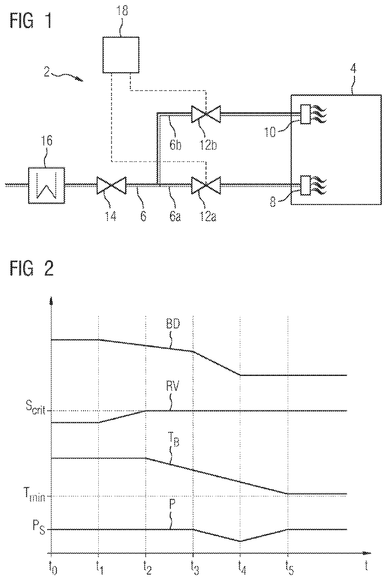
[0022]FIG. 1 schematically shows the structure of a fuel system 2 which is part of a gas turbine plant (not shown in more detail) in which natural gas is used as fuel. The gas turbine plant generally comprises a compressor, a combustion chamber 4 and a gas turbine, coupled to which, for example, is a generator for generating electricity.

[0023]The fuel system 2 comprises a gas line 6 via which gaseous fuel is supplied to the combustion chamber 4. In the combustion chamber 4, there are arranged in particular multiple burners, which, in the exemplary embodiment shown, are of a multi-stage design and which, in the figure, are illustrated symbolically by a main burner 8 and a pilot burner 10. A sub-line 6a, 6b, in which a respective regulating valve 12a, 12b is installed, is branched off to each of the burner stages 8, 10. The gas line 6 moreover contains an emergency valve 14. Upstream of the emergency valve 14, ther...


PUM


Abstract

A method for operating a gas turbine plant with gaseous fuel, which is conveyed to the gas turbine plant through a gas line, burnt in a combustion chamber and then supplied to a gas turbine. At least one valve for controlling the flow of the fuel to the combustion chamber is installed in the gas line, a critical opening position being defined for the valve. To provide an improved method for operating a gas turbine plant in which the power of the gas turbine plant is kept at a maximum for as long as possible in the event of insufficient pressure in the gas line, a temperature of the fuel in the gas line is reduced when the valve is about to exceed the critical opening position.

Description

CROSS REFERENCE TO RELATED APPLICATIONS[0001]This application is the US National Stage of International Application No. PCT / EP2019 / 062589 filed 16 May 2019, and claims the benefit thereof. The International Application claims the benefit of European Application No. EP18182564 filed 10 Jul. 2018. All of the applications are incorporated by reference herein in their entirety.FIELD OF INVENTION[0002]The invention relates to a method for operating a gas turbine plant with gaseous fuel, which is transported through a gas line to the gas turbine plant, is burned in a combustion chamber and is subsequently supplied to a gas turbine. The invention also relates to a control device for carrying out the method, and to a gas turbine plant having such a control device.BACKGROUND OF INVENTION[0003]Gas turbine plants are generally supplied with natural gas, as fuel, via a gas line. Here, the optimum operation of the gas turbine plant is dependent on the quality of the fuel, the correct pressure an...

Claims


Application Information

Patent Timeline
Patent Type & Authority Applications(United States)
IPC IPC(8): F02C9/28F02C7/224
CPCF02C9/28F02C9/32F02C7/224F02C7/14F05D2270/20F05D2270/301F05D2270/303
Inventor BECKMANN, BJÖRNNAUBER, NIKLASOVER, MAARTEN
Owner SIEMENS ENERGY GLOBAL GMBH & CO KG
Why Eureka
Try Eureka