Systems and methods for networking radar detectors

a radar detector and network technology, applied in the field of radar detectors, can solve the problems of short warning time and often not giving the driver enough time to slow down the radar detector

Inactive Publication Date: 2003-05-20
BBN TECHNOLOGIES CORP
View PDF8 Cites 128 Cited by
  • Summary
  • Abstract
  • Description
  • Claims
  • Application Information

AI Technical Summary

Problems solved by technology

One drawback with such a scheme is that the radar detector must be within the range of a functioning radar before it can give

Method used


Image

  • Systems and methods for networking radar detectors
  • Systems and methods for networking radar detectors
  • Systems and methods for networking radar detectors

Examples


Embodiment Construction

refers to the accompanying drawings. The same reference numbers in different drawings may identify the same or similar elements. Also, the following detailed description does not limit the invention. Instead, the scope of the invention is defined by the appended claims and equivalents.

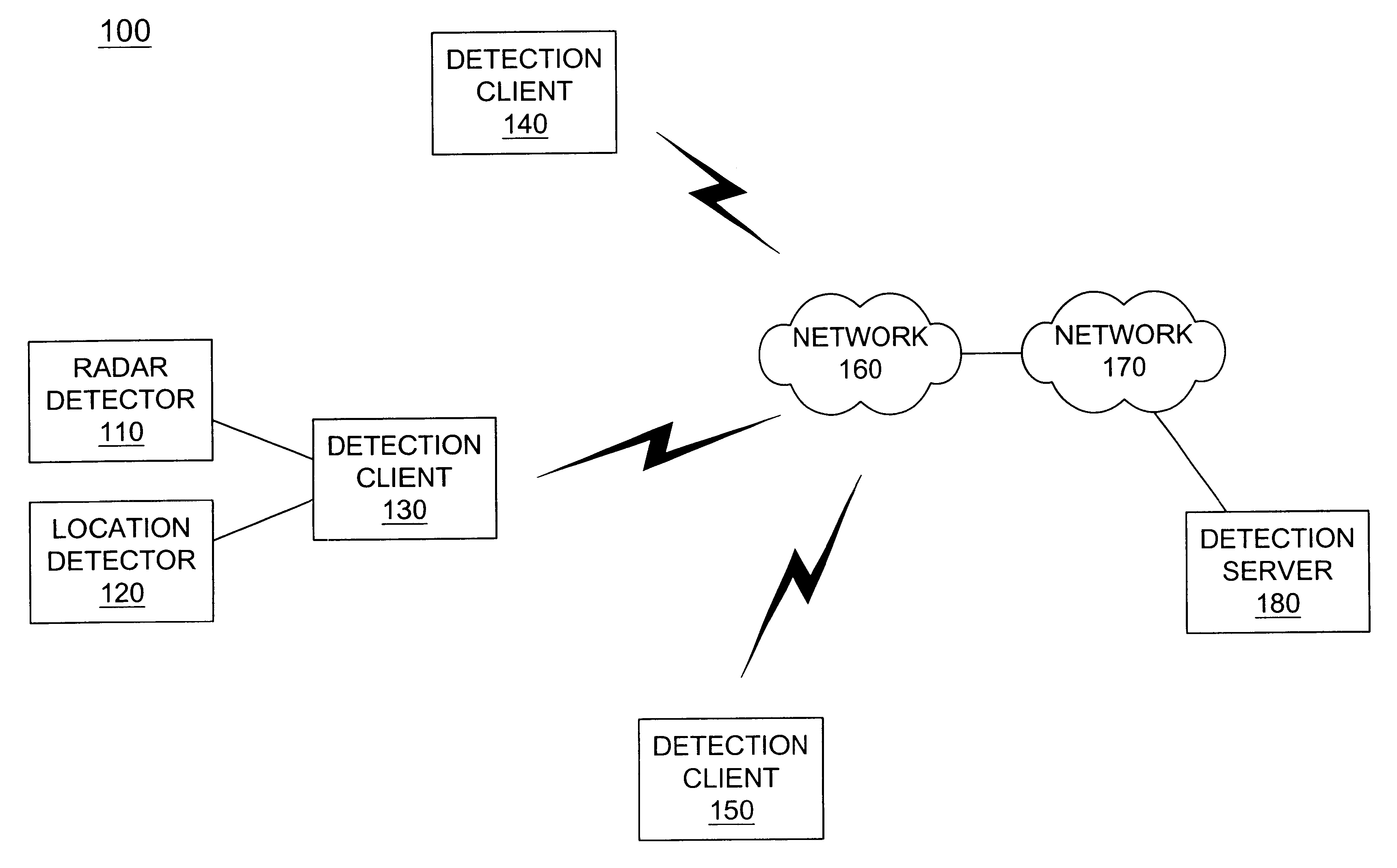
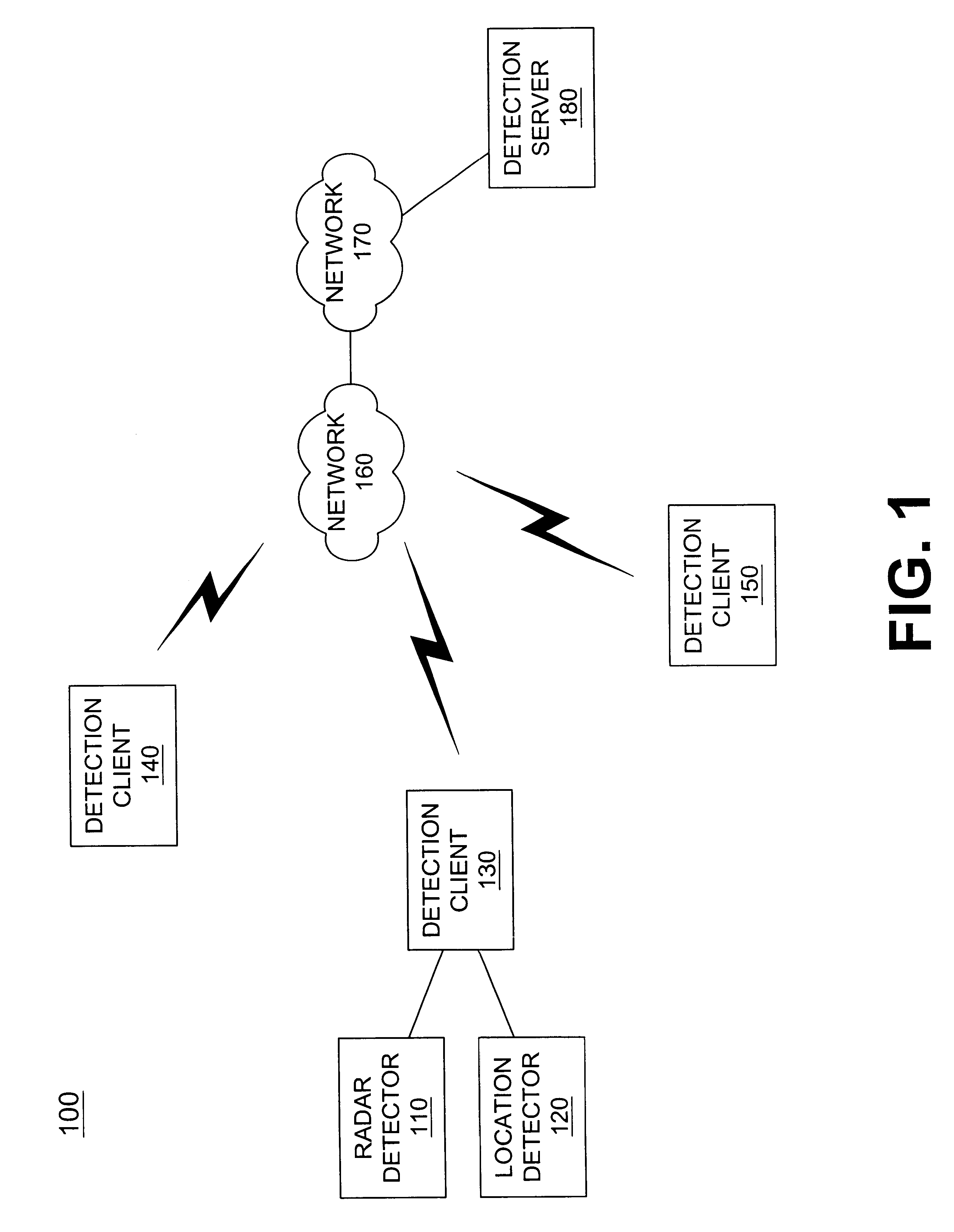
Systems and methods consistent with the present invention enable radar detectors and other detectors to be networked. When one radar detector detects an operating radar, a client device associated with that radar detector transmits a signal via a network to a server. The server may then communicate the radar information to other vehicles. Systems and methods consistent with the present invention also enable police sighting information to be input and transmitted to the server. This police sighting information may also be transmitted to other vehicles.

Exemplary Network

FIG. 1 is a diagram of an exemplary network 100 in which systems and methods consistent with the present invention may be implemented. Ne...


PUM


Abstract

Systems and methods for networking detection devices associated with police activity are provided in a network that includes at least one server (180) and a number of client devices (130-150). Each of the client devices (130-150) transmits its location information to the server for storage. When a client device (130) receives detection information relating to radar activity, a police sighting or other police activity, that client device transmits the detection information to the server (180). The server (180) may then transmit the detection information to other client devices (140,150).

Description

1. Field of the InventionThe present invention relates generally to radar detectors and, more particularly, to networking radar detectors and other detectors.2. Description of Related ArtAt present, radar detectors used in vehicles are stand-alone devices. That is, each radar detector must independently detect radar activity and alert the driver upon the detection. One drawback with such a scheme is that the radar detector must be within the range of a functioning radar before it can give an alert. Typically, the radar detector detects the radar only a short time before the radar device is able to determine the vehicle's speed. The short warning time often does not give the driver enough time to slow down before the vehicle's speed is detected.Therefore, a need exists for systems and methods that provide increased warning of radar activity and / or other police activity.Systems and methods consistent with the present invention address this and other needs by networking a number of det...

Claims


Application Information

Patent Timeline
IPC IPC(8): G01S7/02G01S19/48
CPCG01S7/022H04W4/023H04W4/021
Inventor ELLIOTT, BRIG BARNUM
Owner BBN TECHNOLOGIES CORP
Why Eureka
Try Eureka