Quick-action bar clamp

a bar clamp and quick-action technology, applied in the field of bar clamps, can solve the problems of difficult disengagement of the brake (76) from the slide bar (70)

Inactive Publication Date: 2003-07-01
LI TSUNG HSIANG
View PDF5 Cites 55 Cited by
  • Summary
  • Abstract
  • Description
  • Claims
  • Application Information

AI Technical Summary

Benefits of technology

A quick-action bar clamp in accordance with the present invention includes a non-round slide bar with a series teeth is movable mounted in a body. Clamp means includes a stationary jaw mounted at a top of the body and a movable opposing the stationary jaw is connected to one end of the slide bar. A drive assembly includes a handle formed at a bottom of the body and a trigger opposing the handle pivotally mounted in the body to advance the slide bar by squeezing the trigger toward the handle. A pawl assembly includes a pawl engages with the teeth of the slide bar to prevent a reverse motion of the slide bar when the trigger is released.
Accordingly, an objective of the invention is to provide an improved quick-action bar clamp that provides a nice clamping purpose.
Another objective of the invention is to provide a quick-action bar clamp to release the movable jaw easily when a workpiece is clamped.

Problems solved by technology

When the brake (76) does securely hold the slide bar (70) in position, disengaging the brake (76) from the slide bar (70) is often difficult.

Method used


Image

  • Quick-action bar clamp
  • Quick-action bar clamp
  • Quick-action bar clamp

Examples


Embodiment Construction

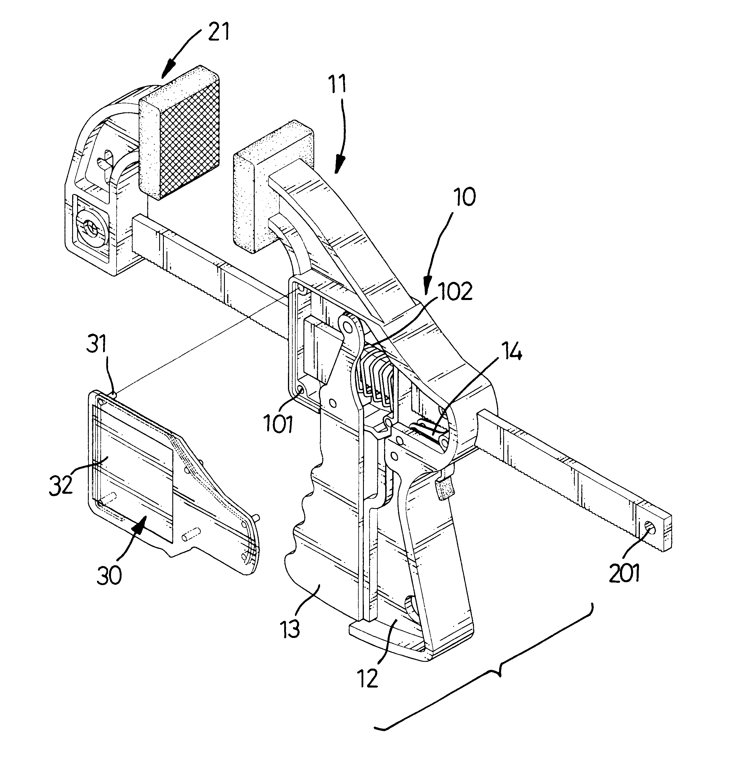
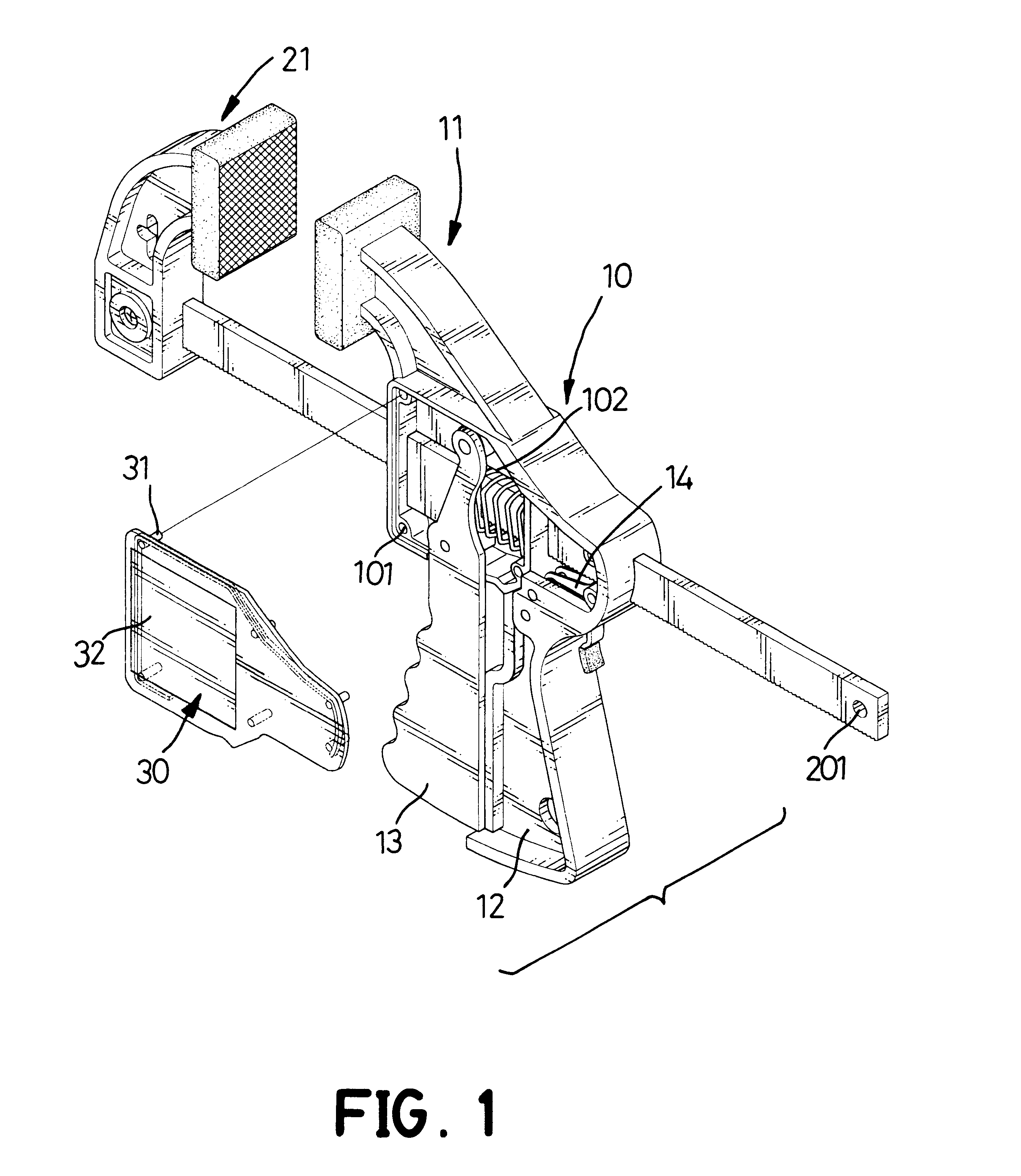
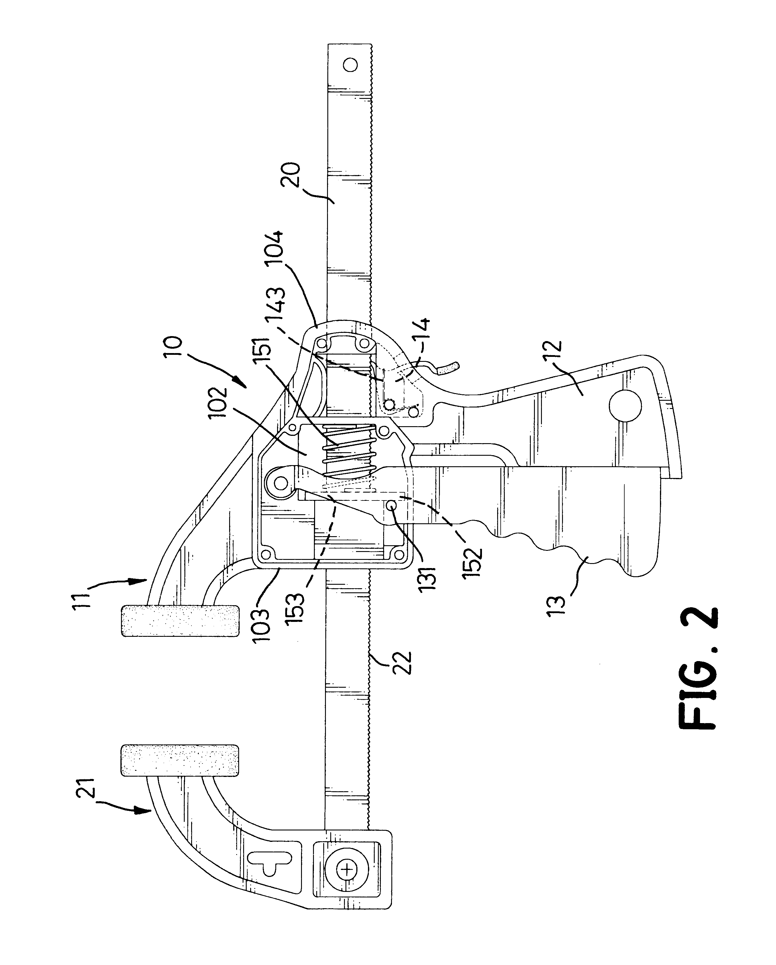
With reference to FIGS. 1 and 2, a quick-action bar clamp in accordance with present invention comprises a body (10), a slide bar (20), clamp means, a drive assembly and a pawl assembly (14).

The body (10) has a top (not numbered), a bottom (not numbered), two sides, a front edge (103), a rear edge (104), a handle (12), a central transverse opening (102), a rear transverse opening (not numbered) and two covers (30). The handle (12) is formed at the bottom of the body (10) and extends down from the body (10). The central transverse opening (102) has a front edge, a rear edge, two sides and several joint holes (101). Joint holes (101) are defined around each side of the central transverse opening (102) respectively. Each cover (30) has stubs (31) corresponding to the joint holes (101) in one side of the central transverse opening (102) respectively and is attached to the side of the body (10) to cover the central transverse opening (102) and the rear transverse opening (102). One of th...


PUM


Abstract

A quick-action bar clamp comprises a body, a slide bar, clamp mechanism, a drive assembly and a pawl assembly. The slide bar has a series of teeth along one edge and is movably mounted in the body. The clamp mechanism includes a stationary jaw mounted on the body and a movable jaw opposing the stationary jaw connected to one end of the slide bar. The drive assembly includes a trigger, a drive lever and a spring. A push pin mounted in the trigger presses the drive lever and moves the slide bar when the trigger is squeezed. The pawl assembly includes a pawl, a release tab, a biasing element and a plastic tag. The pawl engages the teeth on the slide bar to positively hold the slide bar in position when the trigger is released.

Description

1. Field of the InventionThe present invention relates to a bar clamp and more particularly to a quick-action bar clamp with a non-round slide bar with multiple teeth and a pawl assembly to engage with teeth. A movable jaw can be rapidly advanced and released easily when a workpiece is clamped between a movable and a stationary jaw.2. Description of Related ArtA bar clamp operated with one hand is used to clamp two articles together and is more convenient than a bar clamp that requires two hands to operate. With reference to FIG. 8, a conventional bar clamp comprises a slide bar (70), a stationary jaw (71), a movable jaw (72), a body (73), a drive assembly and a brake (76). The movable jaw (72) opposes the stationary jaw (71) and is mounted at one end of the slide bar (70) that is movably mounted through the body (73). The slide bar (70) has a top edge and a bottom edge.The body (73) has a top, a bottom, a front edge, a cavity (731), a transverse hole (732) and a handle (74). The st...

Claims


Application Information

Patent Timeline
Patent Type & Authority Patents(United States)
IPC IPC(8): B25B5/06B25B5/00
CPCB25B5/068
Inventor LI, TSUNG-HSIANG
Owner LI TSUNG HSIANG
Why Eureka
Try Eureka