Link structure between a temple arm and a bracket for eyeglasses

a technology of eyeglasses and temple arms, which is applied in the direction of instruments, spectales/goggles, multi-purpose tools, etc., can solve the problems of affecting the use of eyeglasses. users, and the process of repairing the trouble or the replacement of parts is very difficul

Inactive Publication Date: 2003-07-01
NAGAYOSHI KOJI
View PDF7 Cites 24 Cited by
  • Summary
  • Abstract
  • Description
  • Claims
  • Application Information

AI Technical Summary

Benefits of technology

The inventors of the application endeavored themselves to study the foregoing issues and have found that it is possible to give an adequate resistance to the deployment and folding motion of the temple arm by keeping constantly the link portion of the temple arm with the bracket in contact under pressure with a flexible member having a restoring force (a flexible member), to create a characteristic variation of mode of deploying and folding motion of the temple arm by forming the lateral surface of the link portion in various shapes, and to prevent the falling off of the flexible member by keeping the link portion of the temple arm in contact under pressure with the flexible member. And based on this finding, the inventors completed this invention.

Problems solved by technology

Even if efforts are made to control the easiness of deployment of the temple arm by tightening the screw linking the temple arm and the bracket, the screw tends to become loose and return to the original state sooner or later.
However, the past proposals have in general been based on complicated constructions such as screwing or soldering a small spring to the temple arm or the bracket (see for example Japanese Patent Application Laid Open 1998-133153).
And therefore, the manufacturing process became complicated, or the process of repairing the trouble or the replacement of parts was very difficult for users, and in fact many of them did not allow laymen to repair.
Moreover, the past inventions included those whose link structure was naked and far from being fashionable (see for example Japanese Patent Application Laid Open 1997-133898) and those whose temple arms were unnaturally large (see for example Japanese Patent Application Laid Open 1992-70624), and thus they were not ones that give an impression of being a high-grade product.
This is perhaps a design issue, but considerations must be paid at least not leaving the link structure between the temple arm and the bracket in a naked state and not making the temple arm inordinately large.

Method used


Image

  • Link structure between a temple arm and a bracket for eyeglasses
  • Link structure between a temple arm and a bracket for eyeglasses
  • Link structure between a temple arm and a bracket for eyeglasses

Examples


first embodiment

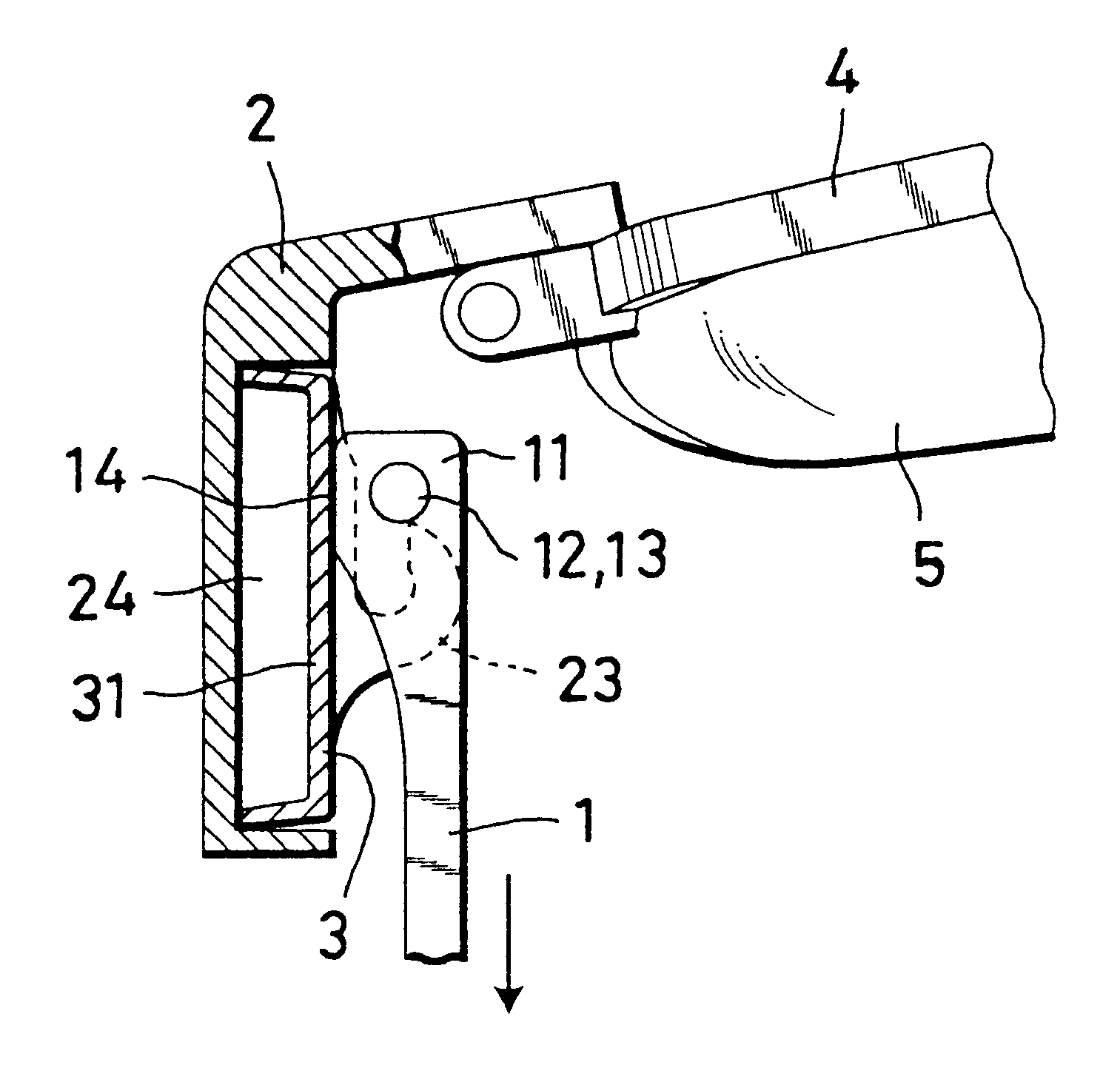
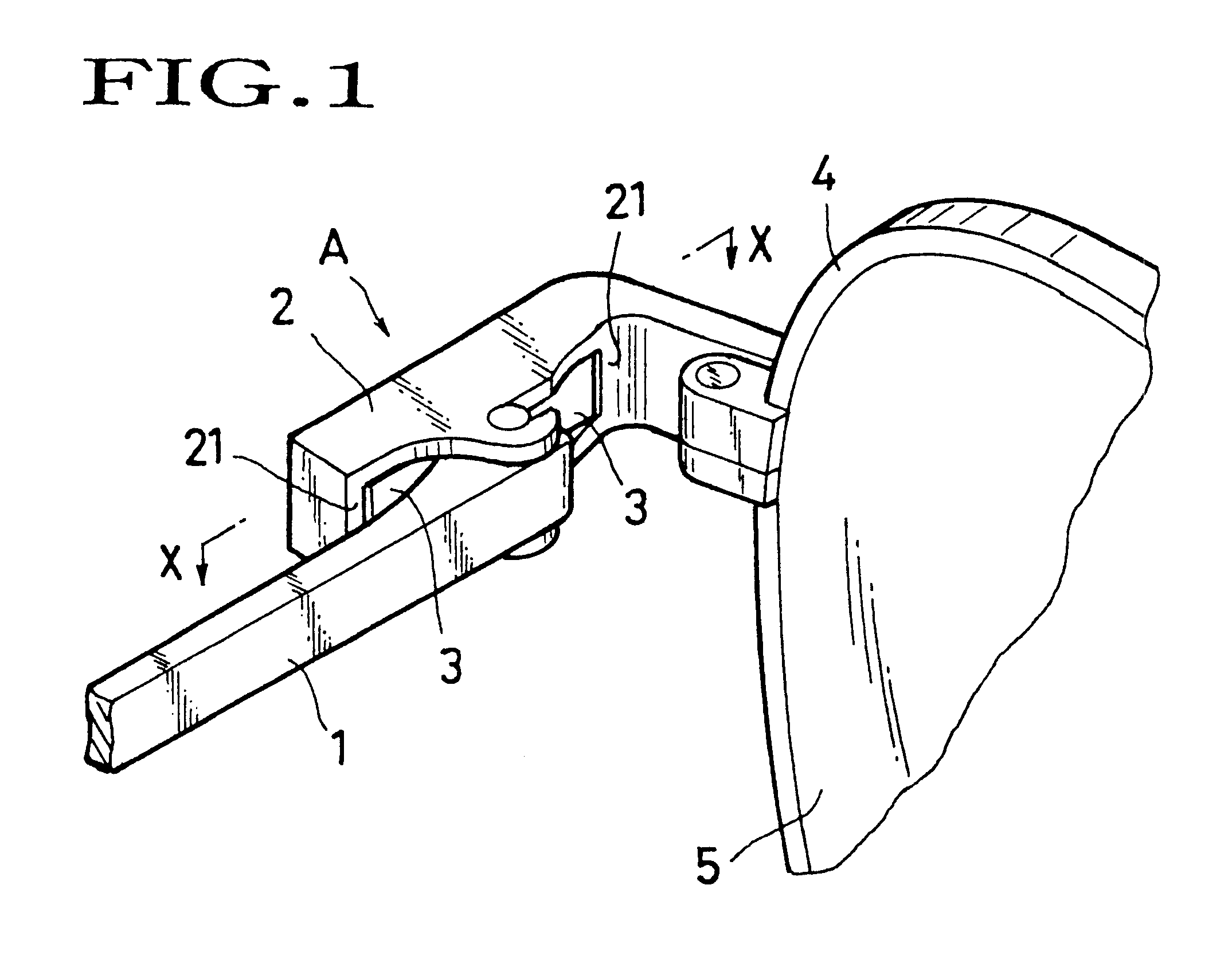
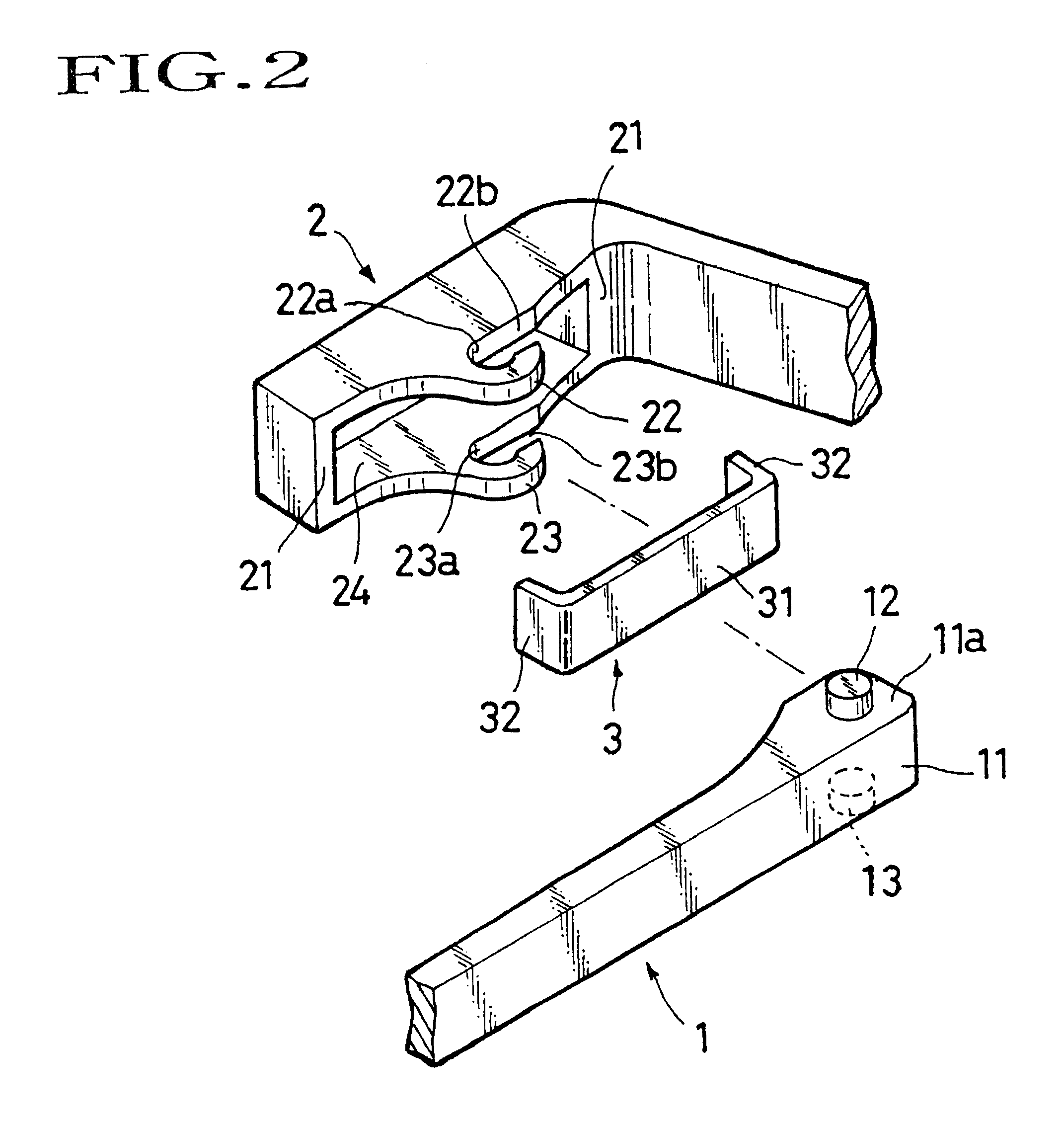
showing an example of construction of the link structure A between a temple arm and a bracket. FIG. 2 is an exploded view showing separately the elements of the link structure between a temple arm and a bracket illustrated in FIG. 1. And FIG. 3 is a view seen from the opposite side of the temple arm illustrated in FIG. 2.

In this way, the link structure A between a temple arm and a bracket according to this invention consists of three members, i.e. temple arm 1, bracket 2 and flexible member 3 as the basic elements. In the first place the shape of each element shall be described below.

A temple arm 1 includes a link portion 11 linking itself with a bracket 2. At the approximate center of the upper surface 11a and the lower surface 11b of the link portion 11, pivots 12 and 13 jut out cylindrically (see FIG. 2). These pivots 12 and 13 serve as the pivot for the rotation of the temple arm 1 and the bracket 2.

The link portion 11 of the temple arm 1 is in contact under pressure with a flex...


PUM


Abstract

The object of this invention is to provide a link structure between a temple arm and a bracket capable of giving an appropriate resistance to the deploying and folding motion of the temple arm and of producing a characteristic variation of deploying and folding motion of the temple arm with the minimum number of parts and without screwing or soldering, to provide a link structure between a temple arm and a bracket presenting a visually simple and esthetic appearance to eyeglasses, and to provide eyeglasses having such a structure. To achieve these ends, a link structure between a temple arm and a bracket for eyeglasses wherein the temple arm comprises a link portion linking itself with the bracket, the bracket comprises link pieces on its inner upper and lower sides and a flexible member between the upper and lower link pieces, the link portion of the temple arm is inserted between the upper and lower link pieces of the bracket to fix rotatably therein, and the link portion of the temple arm and the flexible member are constantly kept in contact under pressure to each other is provided.

Description

1. Field of the InventionThe invention relates to a link structure between a temple arm and a bracket for eyeglasses, more particularly to a link structure between a temple arm and a bracket for eyeglasses presenting an adequate resistance to and producing a characteristic variation of mode of deploying and folding motion of the temple arm.2. Description of the Related ArtEyeglasses whose temple arms deploy and fold easily and naturally under the gravity give an impression of being a cheap product. Even if efforts are made to control the easiness of deployment of the temple arm by tightening the screw linking the temple arm and the bracket, the screw tends to become loose and return to the original state sooner or later. To give an impression of being a high-grade product to eyeglasses, a link structure between a temple arm and a bracket that does not allow any easy deployment and folding of the temple arm is necessary.Therefore, a number of proposals have been made to create an app...

Claims


Application Information

Patent Timeline
Patent Type & Authority Patents(United States)
IPC IPC(8): G02C5/22
CPCG02C5/008G02C5/10G02C5/2209G02C5/2254Y10T16/526G02C2200/08G02C2200/16G02C2200/22
Inventor NAGAYOSHI, KOJI
Owner NAGAYOSHI KOJI
Why Eureka
Try Eureka