Spark plug with multi-layer firing tip

a spark plug and firing tip technology, applied in the field of spark plugs, can solve the problems of spark erosion, reducing the longevity of the spark plug, etc., and achieves the effect of sufficient resistance to spark erosion and corrosion, and reducing the amount of precious metal

Active Publication Date: 2007-05-24
FEDERAL MOGUL WORLD WIDE LLC
View PDF14 Cites 13 Cited by
  • Summary
  • Abstract
  • Description
  • Claims
  • Application Information

AI Technical Summary

Benefits of technology

[0010] In view of the above, the present invention is directed to multilayer firing tip for a spark plug that minimizes the amount of precious metal used while providing su...

Problems solved by technology

Due to the very nature of an internal combustion engine, spark plugs are exposed to many extremes occurring within the engine cylinder, including high temperatures and various corrosive combustion gases, which have traditionally reduced the longevity of the spark plug.
Spark erosion also reduces the longevity of spark plugs.
However, Platinum, Iridium, and alloys thereof are generally very expensive and it is desirable to minimize the amount of material used to provide the spark portion.
Unfortunately, the high voltage and high temperature environment within the combustion chamber can degrade the components of the spark plug, such as through spark erosion.
As the spark plug becomes degraded, the characteristic of the spark may become altered thereby degrading the quality of the spark and resulting combustion.
As the base material is typically a Nickel alloy, it is susceptible to spark erosion which may cause the base material or center electrode to erode away until the precious metal tip falls off.
Any degradation of the plug will affect the quality of the spark and any spark that does not originate from the spark surface on the spark portion but instead originates on the center electrode and passes around the precious metal fir...

Method used


Image

  • Spark plug with multi-layer firing tip
  • Spark plug with multi-layer firing tip
  • Spark plug with multi-layer firing tip

Examples


Embodiment Construction

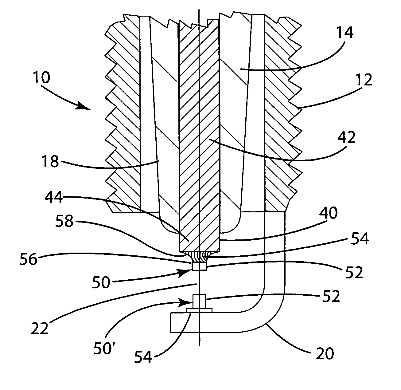
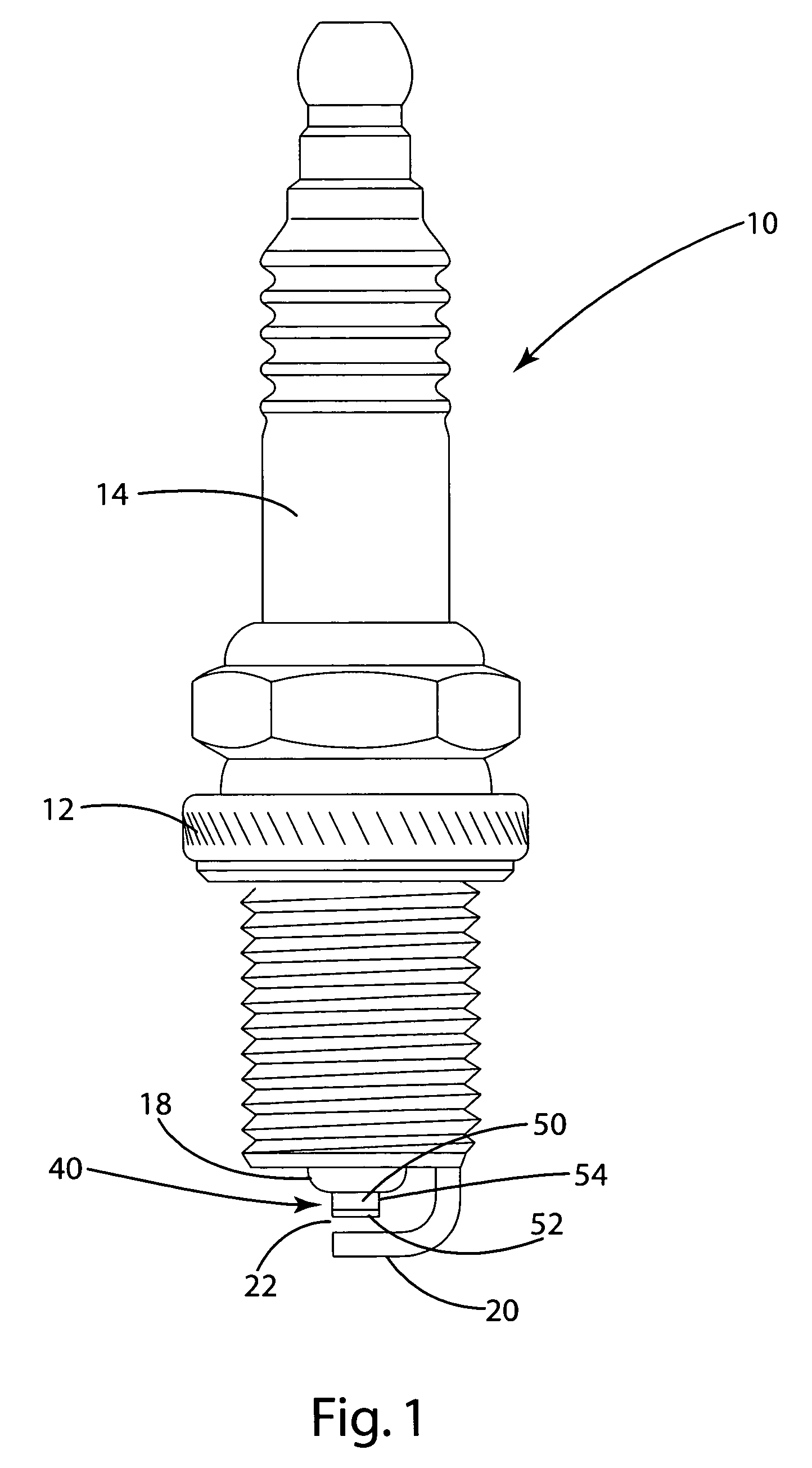
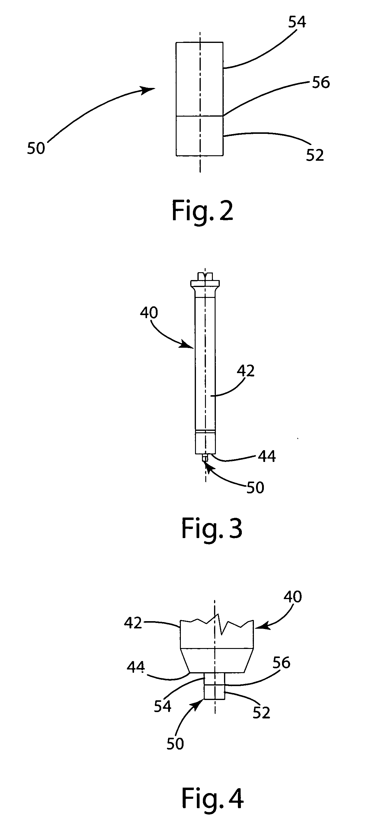
[0029] The present invention relates generally to ignition devices such as spark plug igniters and other spark generation devices. A spark plug 10 is illustrated in front elevational view in FIG. 1. The spark plug 10 includes an outer metallic shell 12 secured to an insulator 14. The outer metallic shell 12 is attached to a ground electrode 20. The insulator 14 has a central bore (not shown) in which a center electrode assembly 40 is situated. The center electrode 40 extends at a firing end 44 beyond the insulator 14 and more specifically beyond the insulator core nose 18. At the firing end 44 of the center electrode assembly 40 a base electrode 42 is situated to which a firing tip 50 is attached facing the ground electrode 20.

[0030] The base electrode 42 as illustrated in the figures extends partially into the combustion chamber and therefore is formed from an alloy that is substantially resistant to corrosion and oxidation. Base electrodes are commonly formed from alloys that inc...


PUM

PropertyMeasurementUnit
Temperatureaaaaaaaaaa
Fractionaaaaaaaaaa
Fractionaaaaaaaaaa

Abstract

A spark plug having a multilayer firing tip that minimizes the amount of precious metal used and a method of assembling a spark plug with a multilayer firing tip. The firing tip includes a discharge end and a weld end, with the weld end being connected to a center electrode, and more specifically to a base electrode on the center electrode. The weld end has a coefficient of thermal expansion, which is not between the values for the coefficients of thermal expansion for the discharge end and the base electrode. More specifically, the weld end has a coefficient of thermal expansion which is greater than the coefficients of thermal expansion for the discharge end and base electrode. The weld end is formed from Nickel and Chromium with a limited amount of additional elements. The spark plug is assembled by providing a first elongated material formed from the material used for the discharge end and a second elongated material formed from a material used for the weld end. The two materials are then joined to form a single joined material and are severed to create a firing tip. The firing tip is welded to the center electrode of the spark plug and more specifically, the base electrode.

Description

CROSS-REFERENCE TO RELATED APPLICATIONS [0001] This application claims priority to U.S. Provisional Application Ser. No. 60 / 772,278, filed Feb. 10, 2006 and U.S. Provisional Application Ser. No. 60 / 737,963, filed Nov. 18, 2005, both of which are incorporated herein by reference.BACKGROUND OF THE INVENTION [0002] 1. Technical Field [0003] This invention is directed to spark plugs and other ignition devices used in internal combustion engines and, more particularly, to ignition devices having high performance metal firing tips. [0004] 2. Related Art [0005] Spark plugs are well known in the industry and have long been used to initiate combustion in internal combustion engines. In general, a spark plug is a device that extends into a combustion chamber of an internal combustion engine and enables a spark to ignite a combustible mixture of air and fuel therein. Specifically, a spark plug typically includes a cylindrical metal shell having external threads that screw into a portion of the...

Claims


Application Information

Patent Timeline
IPC IPC(8): H01T13/20
CPCH01R13/03H01T13/20H01T13/39H01T21/02Y10T29/49147Y10T29/49204Y10T29/49117Y10T29/5195Y10T29/49169Y10T29/49002H01T13/04
Inventor LYKOWSKI, JAMES D.
Owner FEDERAL MOGUL WORLD WIDE LLC
Why Eureka
Try Eureka