Mask patterns including gel layers for semiconductor device fabrication and methods of forming the same

Inactive Publication Date: 2006-03-23
SAMSUNG ELECTRONICS CO LTD
View PDF8 Cites 14 Cited by
  • Summary
  • Abstract
  • Description
  • Claims
  • Application Information

AI Technical Summary

Benefits of technology

[0009] According to some embodiments of the invention, the mask pattern includes a resist pattern, and a gel layer formed on a surface of the resist pattern having a junction comprising hydrogen bonds between a proton donor polymer and a proton acceptor polymer. In some embodiments, the junction of the gel layer includes a plurality of regions capable of undergoing hydrogen bonding and wherein the proton donor polymer and the proton acceptor polymer are hydrog

Problems solved by technology

Short-wavelength exposure based lithography may present difficulties in that this process can be material-dependent and uneconomical.
In particular, half-tone phase shift mas

Method used


Image

  • Mask patterns including gel layers for semiconductor device fabrication and methods of forming the same
  • Mask patterns including gel layers for semiconductor device fabrication and methods of forming the same
  • Mask patterns including gel layers for semiconductor device fabrication and methods of forming the same

Examples


Example

EXAMPLE 1

Formation of Resist Pattern

[0083] An antireflective film (DUV-30, Nissan Chemical Industries, Ltd.) was formed to a thickness of about 360 Å on an 8-inch bare silicon wafer. A photoresist for ArF (SAIL-G24c, ShinEtsu Chemical Co. Ltd) was subsequently spin-coated on the antireflective film followed by baking at about 105° C. for about 60 seconds to form a resist film with a thickness of about 3,000 Å. The resist film was exposed to light by an ArF (193 nm) stepper followed by post-exposure baking (PEB) at about 105° C. for about 60 seconds. The wafer was developed with a 2.38 wt % tetramethylammonium hydroxide (TMAH) solution to form, on the wafer, a resist pattern having a plurality of openings. The resist pattern had an isolated hole pattern (hereinafter, referred to as “i-hole pattern”) with a diameter of 129.7 nm and a dense hole pattern (hereinafter, referred to as “d-hole pattern”) with a diameter of 138.0 nm selected at a center portion of a hole array in which a p...

Example

EXAMPLE 2

Control

Preparation of Coating Composition

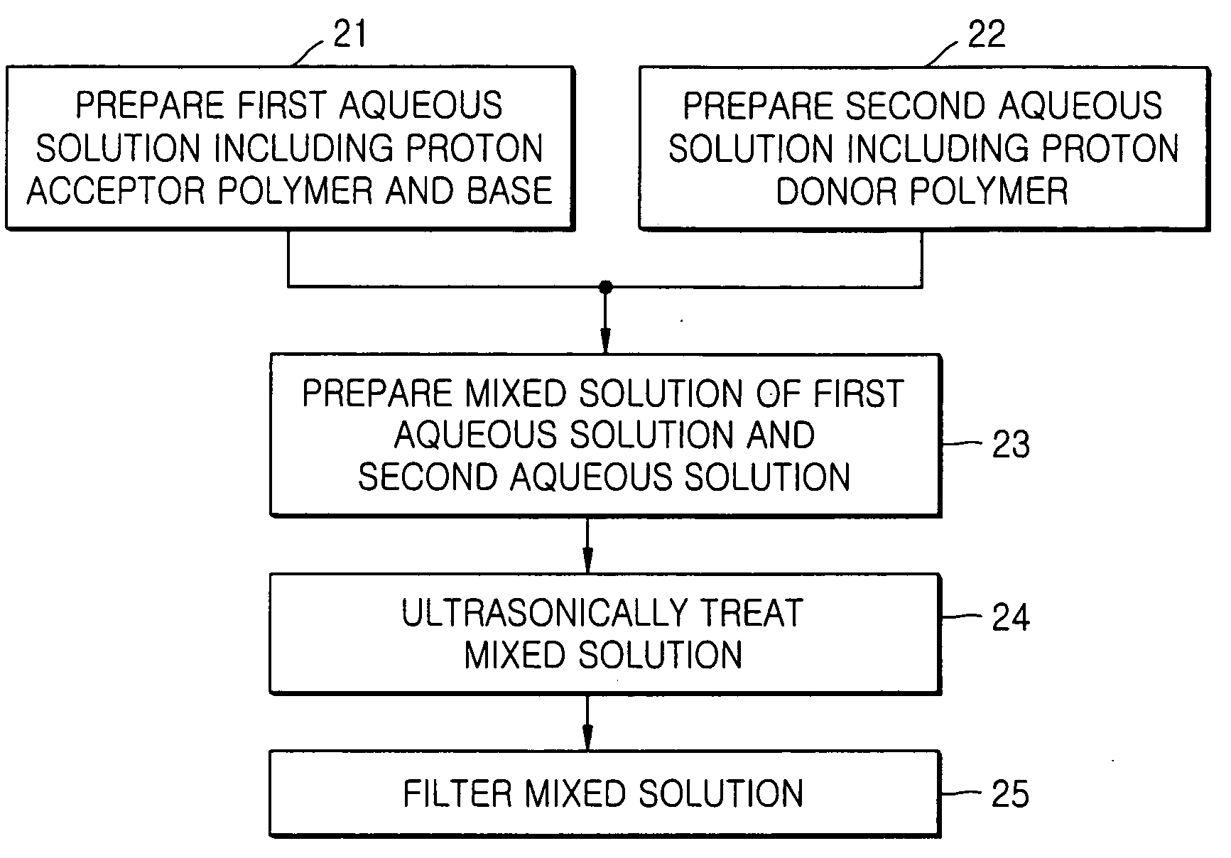
[0090] A solution of 35 mg of TEA in 3,465 mg H2O, a solution of 4.0 mg of Zonyl FSN in 396 mg H2O, and 100 mg H2O were added to a solution of 100 mg of poly(vinylpyrrolidone) in 900 mg H2O to obtain a first aqueous solution. A second aqueous solution of 100 mg of an unprotected poly(acrylic acid-co-maleic acid) in 900 mg H2O, unlike in Example 1, was added dropwise to the first aqueous solution with vigorously stirring. The resultant solution was filtered to provide a clean coating composition. The LCST of the coating composition was about 50° C. To obtain a clear aqueous solution, TEA was used in an amount of 17 wt %, based on the total amount of a resin used. Such an increase in the amount of the base used to obtain a clear aqueous solution in this Example, relative to the amount of the base used in Example 1, can be explained by use of the unprotected poly(acrylic acid-co-maleic acid).

[0091] Formation of Gel Layer

[0092] The ...

Example

EXAMPLE 3

Formation of Resist Pattern

[0093] A resist pattern was formed in the same manner as described in Example 1 except that PEB was performed at 115° C. for about 60 seconds. The resist pattern included an i-hole pattern with a diameter of 174.8 nm and a d-hole pattern with a diameter of 134.7 nm.

[0094] Preparation of 10% t-butyl Protected poly(acrylic acid-co-maleic acid) by Esterification

[0095] Poly(acrylic acid-co-maleic acid) (370 mg), N,N′-dicyclohexylcarbodiimide (10 mg), 4-(dimethylamino)pyridine (3.0 mg), and t-BuOH (2.0 g) were stirred at 23° C. for 4 hours and subjected to precipitation with excess hexane. A supernatant was decanted and the remaining solid was dried under vacuum at 30° C. overnight to provide 10% t-butyl protected poly(acrylic acid-co-maleic acid) (319 mg) as a white solid.

[0096] Preparation of Coating Composition

[0097] A solution of 5.2 mg of tetramethylammonium hydroxide (TMAH) in 215 mg H2O, a solution of 1.0 mg of Zonyl FSN in 99 mg H2O, and ...


PUM


Abstract

Mask patterns include a resist pattern and a gel layer on a surface of the resist pattern having a junction including hydrogen bonds between a proton donor polymer and a proton acceptor polymer. Methods of forming the mask patterns and methods of fabricating a semiconductor device using the mask patterns as etching masks are also provided.

Description

RELATED APPLICATION DATA [0001] This application claims priority from Korean Patent Application No. 10-2004-0076350, filed Sep. 23, 2004, the disclosure of which is incorporated herein by reference in its entirety. FIELD OF THE INVENTION [0002] The present invention relates to mask patterns. More particularly, the present invention relates to mask patterns for fabrication of a semiconductor device, methods of forming the same and methods of fabricating a semiconductor device using the mask patterns as etching masks. BACKGROUND OF THE INVENTION [0003] In a conventional patterning process for semiconductor device fabrication, after a photoresist pattern is formed on a predetermined film to be etched for pattern formation, for example, a silicon film, a dielectric film, or a conductive film, the predetermined film may be etched by using the photoresist pattern as an etching mask to form a desired pattern. [0004] With the increased integration of semiconductor devices, it is desirable t...

Claims


Application Information

Patent Timeline
IPC IPC(8): G03C5/00G03C1/494G03C1/492G03C1/76G03F1/00G03F7/40H01L21/027
CPCG03F7/023G03F7/40G03F7/0392G03F7/0382H01L21/0273
Inventor HATA, MITSUHIROKIM, HYUN-WOOHAH, JUNG-HWANWOO, SANG-GYUN
Owner SAMSUNG ELECTRONICS CO LTD
Why Eureka
Try Eureka