Armrest structure for vehicle
- Summary
- Abstract
- Description
- Claims
- Application Information
AI Technical Summary
Benefits of technology
Problems solved by technology
Method used
Image
Examples
embodiment 1
[0100] Embodiment 1
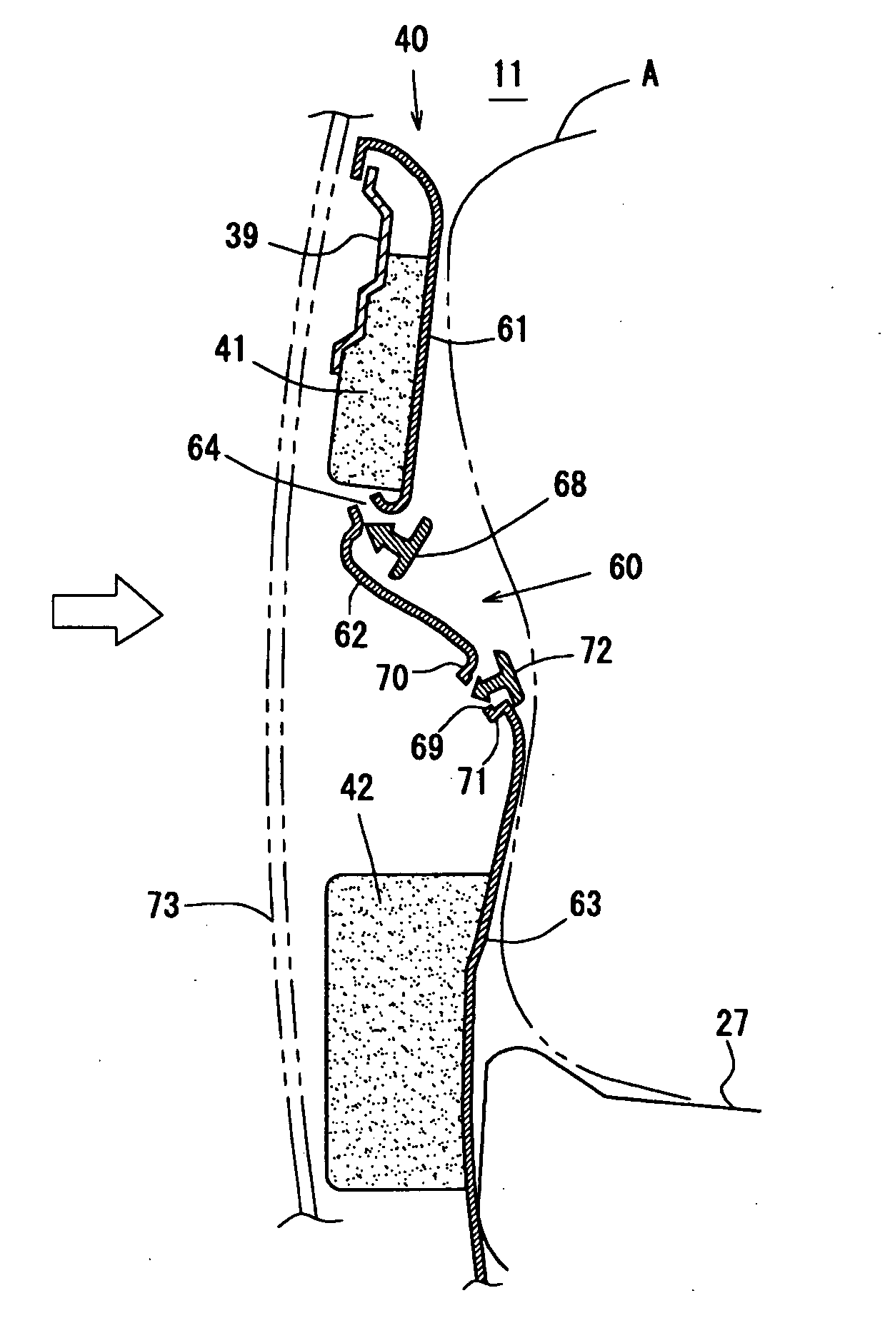
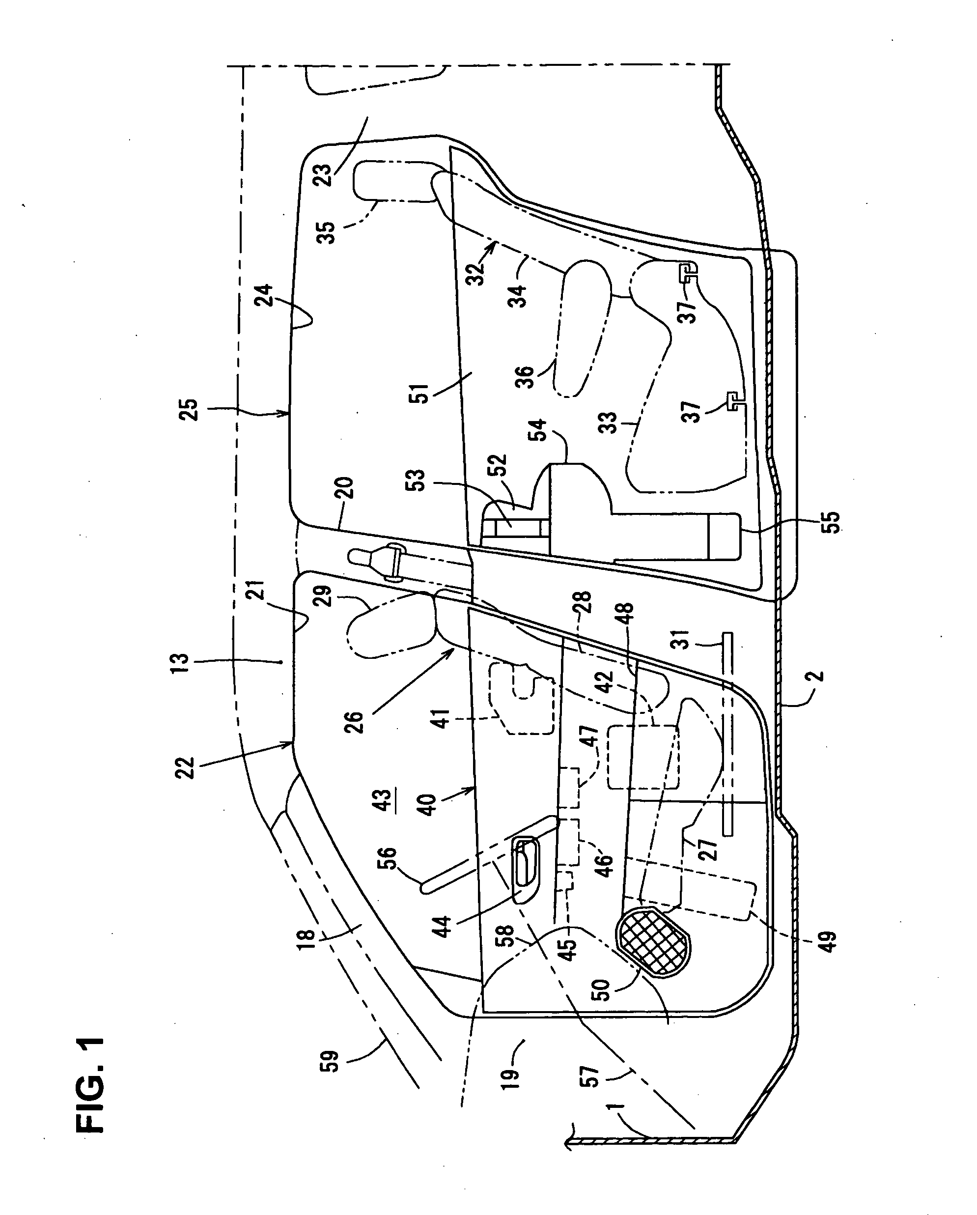
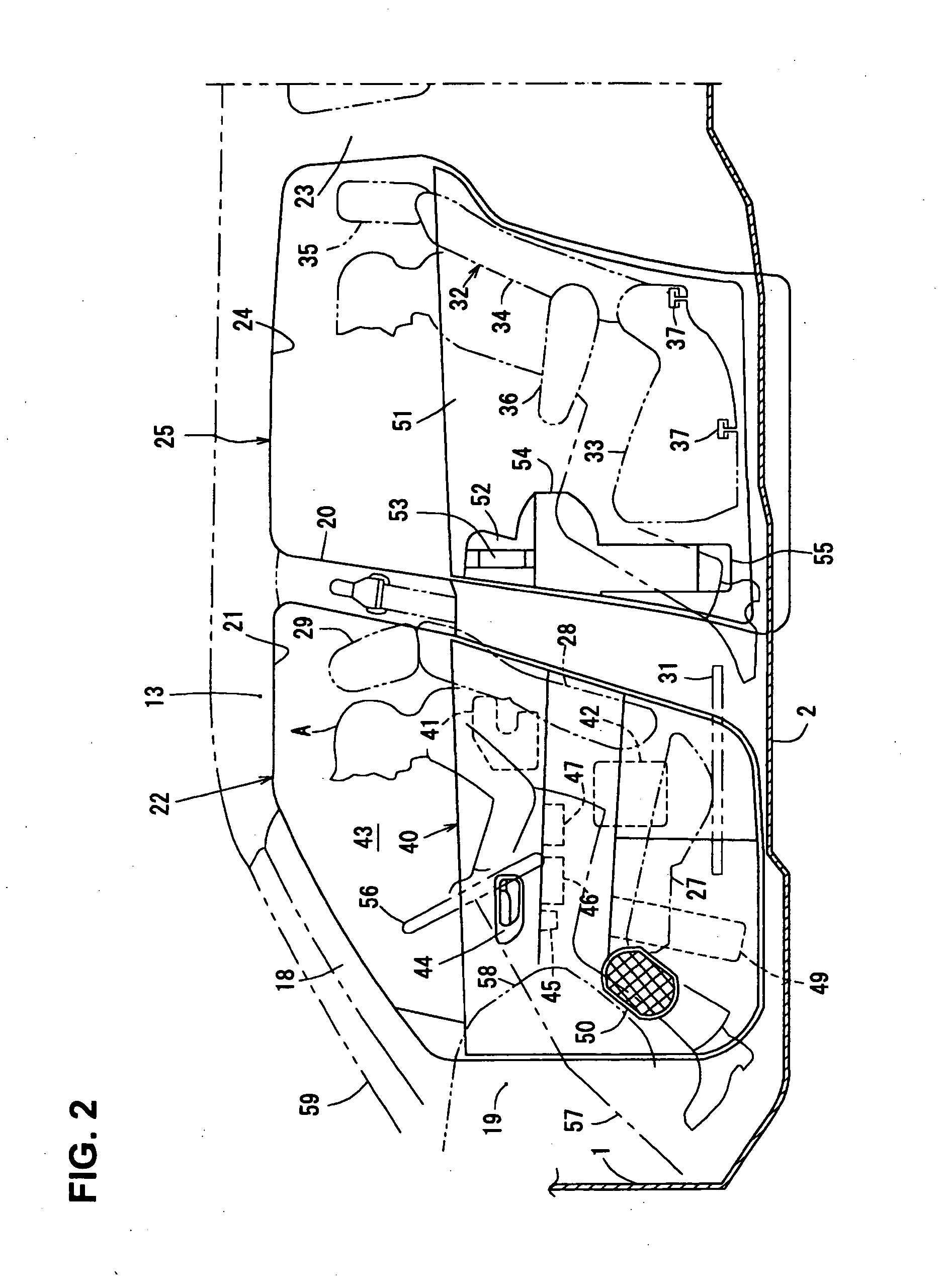
[0101] An armrest structure for a vehicle according to a first embodiment will be described referring to FIGS. 4, 5 and 6.
[0102] The above-described door trim 40 is provided with an armrest 60 formed integrally with the door trim 40 which protrudes and extends toward the passenger A from an inside wall (the door inner panel 39 of the front door 22 in the embodiment) of the vehicle compartment 11.
[0103] The armrest 60 comprises a trim body portion 61 (upper portion of the door trim 40) which covers the inside wall of the vehicle compartment, an armrest face portion 62 for armrest of the passenger A which extends in a substantially horizontal direction from the trim body portion 61 toward the inside of the vehicle compartment 11 by a specified length L1 (a necessary length for passengers to put their arms), and a support face portion 63 which extends continuously from the armrest face portion 62 downward.
[0104] Herein, as illustrated in FIGS. 5 and 6, there are p...
embodiment 2
[0134] Embodiment 2
[0135] An armrest structure for a vehicle according to a second embodiment will be described referring to FIGS. 10, 11 and 12.
[0136] The above-described door trim 140 is provided with an armrest 160 formed integrally with the door trim 140 which protrudes and extends toward the passenger A from an inside wall (the door inner panel 39 of the front door 22 in the embodiment) of the vehicle compartment 11.
[0137] The armrest 160 comprises a trim body portion 161 (upper portion of the door trim 140) which covers the inside wall of the vehicle compartment, an armrest face portion 162 for armrest of the passenger A which extends in the substantially horizontal direction from the trim body portion 161 toward the inside of the vehicle compartment 11 by the specified length L1 (a necessary length for passengers to put their arms), and a support face portion 163 which extends continuously from the armrest face portion 162 downward.
[0138] There are provided first openings ...
embodiment 3
[0156] Embodiment 3
[0157]FIG. 14 illustrates a third embodiment of the present invention. Herein, the thickness t2 (see FIG. 14) of the door trim 240 of the present embodiment is set to be thicker than the thickness t1 (see FIG. 10) of the door trim 140 of the previous embodiment (t2>t1). Further, there are provided notch portions 272, 273, 274 at the bottom face of the connecting piece 265 remaining between the first openings 164 . . . 164 (see FIG. 11), which are located at portions corresponding to the opening edge (end portions in the vehicle width direction) of the first openings 164 . . . 164 and at the middle portion of the connecting piece 265 in the vehicle width direction. Other structures of the present embodiment illustrated in FIG. 14 are the same as those of the previous embodiment.
[0158] In the present embodiment, the load resistance of the armrest in use in the vertical direction can be further improved by the door trim 240 with the thickness of t2. Further, the rig...
PUM
 Abstract
Description
Claims
Application Information
 - R&D
- Intellectual Property
- Life Sciences
- Materials
- Tech Scout
- Unparalleled Data Quality
- Higher Quality Content
- 60% Fewer Hallucinations
Browse by: Latest US Patents, China's latest patents, Technical Efficacy Thesaurus, Application Domain, Technology Topic, Popular Technical Reports.
© 2025 PatSnap. All rights reserved.Legal|Privacy policy|Modern Slavery Act Transparency Statement|Sitemap|About US| Contact US: help@patsnap.com


