
A tensioning support device

A support device and tensioning technology, applied in the direction of low internal friction spring, vibration suppression adjustment, spring/shock absorber, etc., can solve the vibration isolation and vibration reduction of precision instrument platforms, the influence of working platform positioning accuracy, and structural deformation. and other problems, to achieve the effect of easy installation, adjustment and post-maintenance, simple and detachable connection, and adjustment of support stiffness.

Active Publication Date: 2022-08-02
CENT SOUTH UNIV +1
View PDF12 Cites 0 Cited by
  • Summary
  • Abstract
  • Description
  • Claims
  • Application Information

AI Technical Summary

Problems solved by technology

For example, Chinese Invention Patent Application 202010494535.4 "A Prismatic Tensile Integral Quasi-Zero Stiffness Vibration Isolator", the coil spring used to provide positive stiffness is directly connected to the bearing platform and the base along the vertical direction, and can be used in the vertical direction Stiffness control, but for impacts from other directions, the vibration damping effect cannot be achieved
Another example is the Chinese patent ZL201611002397.3 "A Tensile Integral Vibration Isolation Mechanism", which can achieve multi-directional vibration reduction, but it uses a rigid-flexible mixed branch chain connected in series with a compression spring to support the working platform, and the compression deformation direction of the spring is the same as the The direction of the supporting force provided by the rigid-flexible mixed branch chain coincides, so there is a problem of insufficient structural rigidity, and in the case of external oblique vibration impact, the spring may be subjected to shear force and cannot provide support; secondly, the piston The rod and the spring are fixed by welding, which is not conducive to later maintenance, and is prone to structural deformation during welding, which has a great impact on the positioning accuracy of the working platform; The lower end is fixedly connected, and there is also the problem of inconvenient installation; although the hydraulic drive device used can achieve multi-directional vibration reduction and active folding, it will greatly increase the weight of the entire structure, and it also has a high impact on the hydraulic system circuit and control. Requirements, and the hydraulic drive control accuracy is generally not high, so it is not suitable for vibration isolation and vibration reduction of precision instrument platforms

Method used


Image

  • A tensioning support device
  • A tensioning support device
  • A tensioning support device

Examples


Embodiment Construction

[0019] In order for those skilled in the art to better understand the technical solutions in the embodiments of the present invention, and to make the above objects, features and advantages of the present invention more clearly understood, the specific embodiments of the present invention are further described below with reference to the accompanying drawings. illustrate.

[0020] It should be noted here that the descriptions of these embodiments are used to help the understanding of the present invention, but do not constitute a limitation of the present invention. In addition, the technical features involved in the various embodiments of the present invention described below can be combined with each other as long as they do not conflict with each other.

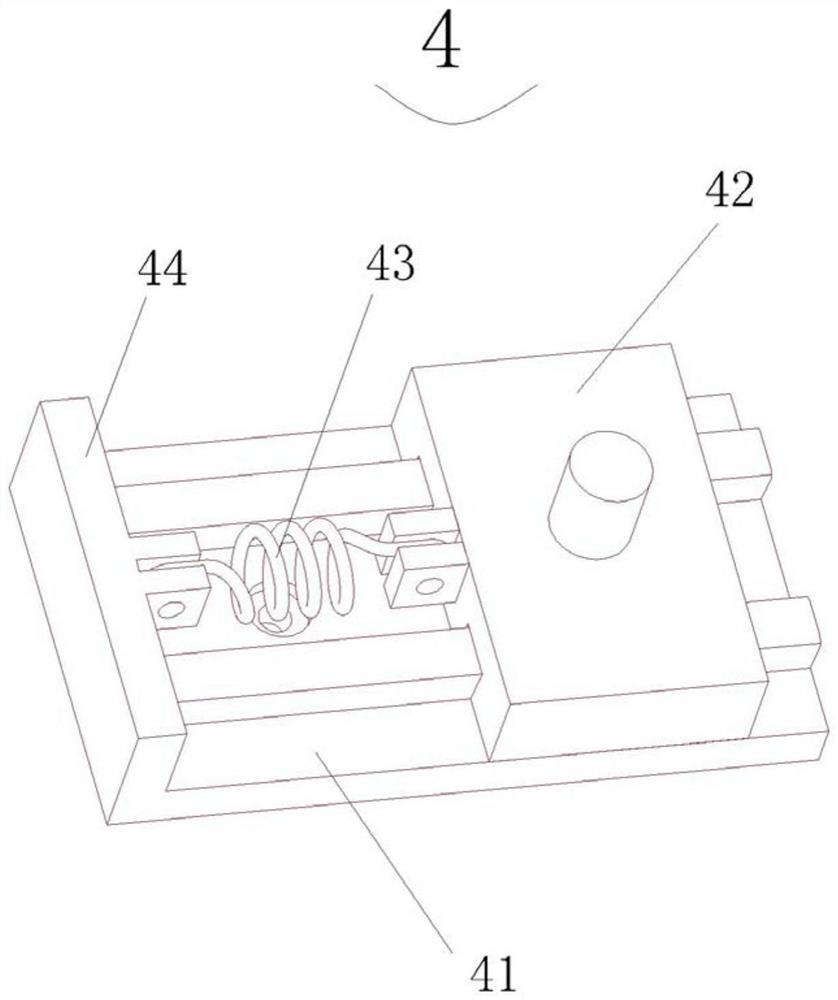
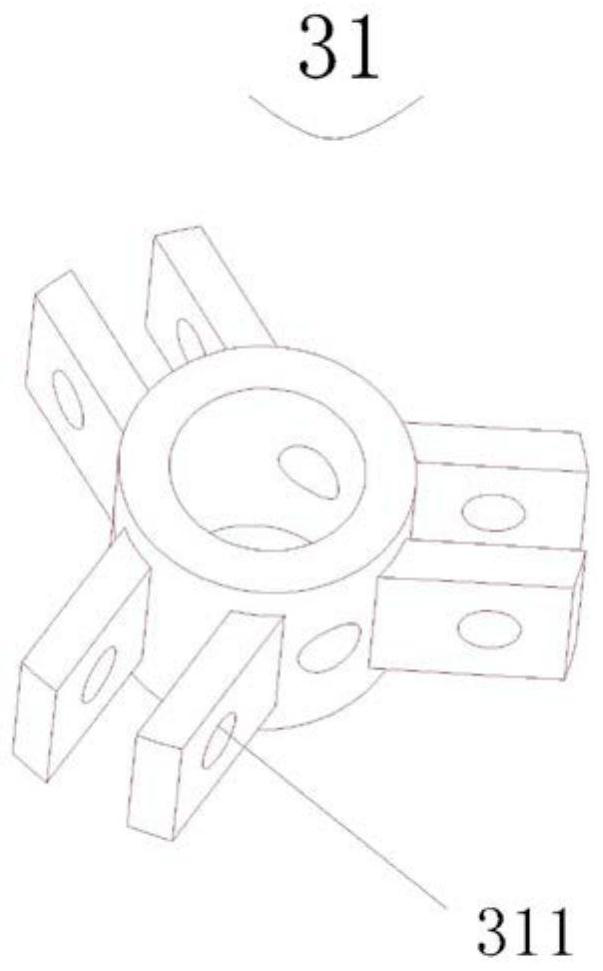
[0021] A tensioning support device of this embodiment is combined with reference to Figure 1 to Figure 4 , the tensioning support device includes: a load platform 1, a base platform 2, three support rods 3 and three sets...


PUM


Abstract

The invention discloses a tensioning support device, comprising: a load platform, a foundation platform, three support rods and three sets of pressure-bearing sliding block devices. Between the base platforms; the pressure-bearing sliding block device includes a guide rail base, a sliding block, a lower buffer spring and a sliding block tail block, the lower ends of the three supporting rods are hinged to the sliding block through universal joints, and the upper They are hinged with the load platform respectively through universal joints; the upper ends of the three support rods are connected by upper tension springs, and the initial state of the three upper tension springs is a stretched state; the adjacent upper and lower ends of the three support rods are connected. The ends are connected in a staggered manner by means of cable-stayed tensioning. It makes full use of the characteristics of light weight, simple structure and compact size of the overall structure of the three-bar support rod. Compression to achieve the purpose of vibration reduction.

Description

technical field [0001] The present invention relates to the technical field of vibration damping devices, in particular to a tensioning support device. Background technique [0002] In the technical fields of rail transit, aerospace, national defense and military industries, the requirements for vibration and noise reduction, safety and comfort, prolonging service life, and resistance to vibration fatigue and impact interference are getting higher and higher. The development of technology faces new challenges. For example, shipborne and airborne equipment are easily affected by the interference of foundation vibration, resulting in unstable working performance, so there is an urgent need for vibration and vibration isolation devices. At present, shipborne and airborne equipment mainly use unidirectional vibration damping devices such as wire ropes or springs, but they lack the effect of multidirectional vibration damping. The existing multi-directional vibration damping de...

Claims


Application Information

Patent Timeline
Patent Type & Authority Patents(China)
IPC IPC(8): F16F15/067F16F3/04
CPCF16F15/067F16F3/04
Inventor 郭彬谭建平牛浩冯国帅常世荣王若枫
Owner CENT SOUTH UNIV
Learn More