Fabrication method of high precision, thermally stable electromagnetic coil vanes

a technology of thermal stability and fabrication method, which is applied in the manufacture of electrode systems, magnetic bodies, electric discharge tubes/lamps, etc., can solve the problems of time consumption, difficulty and time involved, and current methods used for winding coils are difficult and time-consuming

Inactive Publication Date: 2003-07-08
NIKON CORP
View PDF26 Cites 4 Cited by
  • Summary
  • Abstract
  • Description
  • Claims
  • Application Information

AI Technical Summary

Problems solved by technology

As the number of radially cut grooves and the number of turns increases, so does the degree of difficulty and the time involved.
Accordingly, current methods used for winding coils is difficult and time consuming, particularly when the number of offset grooves and turns increases.

Method used


Image

  • Fabrication method of high precision, thermally stable electromagnetic coil vanes
  • Fabrication method of high precision, thermally stable electromagnetic coil vanes
  • Fabrication method of high precision, thermally stable electromagnetic coil vanes

Examples


Embodiment Construction

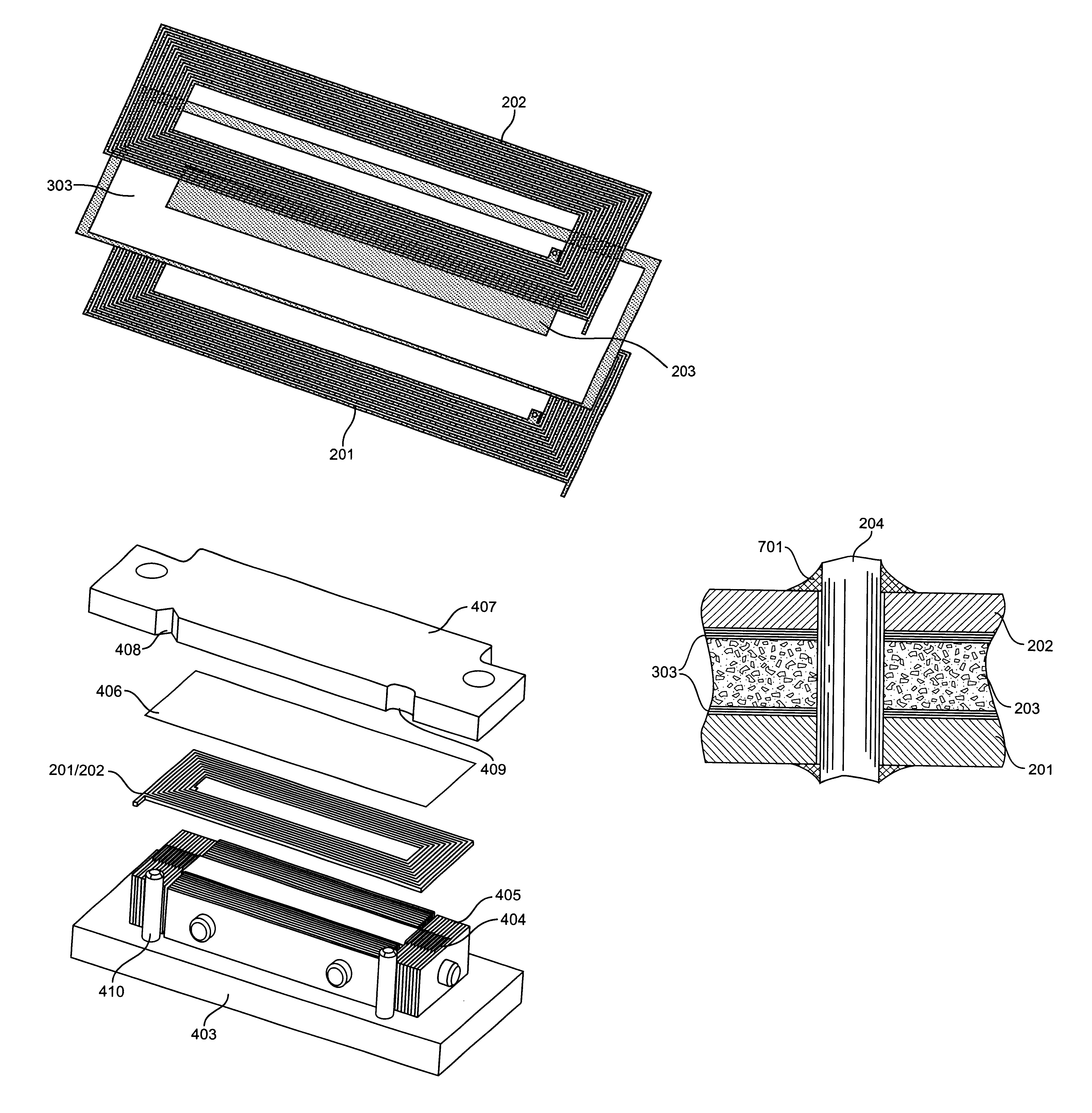
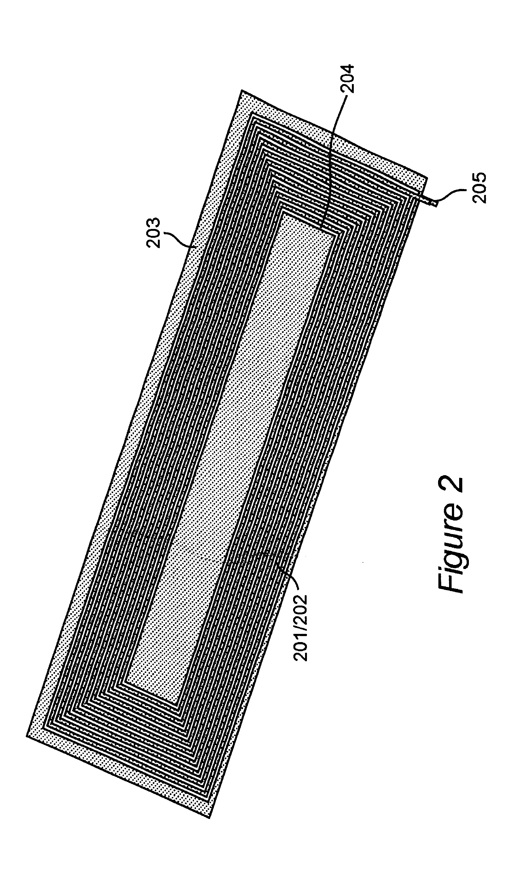
Referring now to the drawings, and specifically to FIGS. 2 and 3, an electromagnetic coil vane is shown. In a preferred embodiment, the electromagnetic coil vane requires two complimentary copper coil patterns 201 and 202 of preferably approximately 22-23 AWG, uninsulated rectangular cross section wire. The complementary coil patterns 201 and 202 are then accurately bonded to opposing sides of a thin substrate 203. The substrate preferably has a low coefficient of thermal expansion (CTE). Other wires and substrates may also equally be used with the present invention, depending on the particular application. For example, Zerodur.RTM., produced by Schott Glaswerke (Mainz, Germany) may also be used as a substrate. The two complementary copper coil patterns 201 and 202 are connected by a through wire 204. The through wire extends through substrate 203 and is connected to coils 201 and 202 to provide an electrical connection between them. The gaps between adjacent copper wires for patter...


PUM

PropertyMeasurementUnit
sizeaaaaaaaaaa
coefficient of thermal expansionaaaaaaaaaa
widthaaaaaaaaaa

Abstract

The present invention relates to a method and apparatus of fabricating electromagnetic coil vanes. The method involves placing a bonding composition on opposing surfaces of a substrate. First and second complementary coil patterns are formed, and are aligned and bonded to respective clamp plate fixtures. The first complementary coil pattern is bonded to one surface of the opposing surfaces of the substrate via the bonding composition, and the second complementary coil pattern is bonded to the other surface of the opposing surfaces of the substrate via the bonding composition. The bonding composition is cured, and the clamp plates are removed from the first and second complementary coil patterns.

Description

DESCRIPTION1. Field of the InventionThe present invention generally relates to a method and apparatus of fabricating electromagnetic coil vanes and, more particularly, to a method and apparatus for fabricating high precision, thermally stable electromagnetic coil vanes used with Charged Particle Beam Projection Systems.2. Background DescriptionYokes and electromagnetic lenses are widely used in electron beam tools, electron microscopes, and cathode ray tubes. Yokes and lenses employing toroidal magnetic deflection coils are commonly used in electron beam lithography systems for focusing an electron beam on to a substrate for submicron patterning of semiconductor devices.U.S. Pat. No. 4,251,728 to Pfeiffer shows an example of a toroidal magnetic deflection yoke. FIG. 1 shows a top view of a traditional toroidal yoke similar to that shown in Pfeiffer. The traditional yoke includes a plastic form having slots numbered from 1 to 20, and forms both X and Y coil axes.Presently, electromag...

Claims


Application Information

Patent Timeline
Patent Type & Authority Patents(United States)
IPC IPC(8): H01J9/236H01J9/00H01F41/04H01J37/141H01J37/147
CPCH01J9/236H01J2237/152Y10T29/49128Y10T29/4902Y10T29/49117Y10T29/49073
Inventor KENDALL, RODNEY A.PICKNEY, DAVID A.
Owner NIKON CORP
Why Eureka
Try Eureka