
Molded case circuit breaker

a circuit breaker and molded case technology, applied in the direction of circuit breaker contacts, circuit breaker switches, contact mechanisms, etc., can solve the problems of cumbersome procedure for mounting pressure springs 11 and complex structur

Inactive Publication Date: 2003-07-08
FUJI ELECTRIC FA COMPONENTS & SYST CO LTD
View PDF3 Cites 25 Cited by
  • Summary
  • Abstract
  • Description
  • Claims
  • Application Information

AI Technical Summary

Benefits of technology

To attain the objects, the present invention provides a molded case circuit breaker having a current-interrupting section in a main body case of the circuit breaker. The current-interrupting section is composed of an assembly of an insulated case; an arc-extinguishing device; a power-supply side and load side fixed contact shoes diagonally arranged with respect to each other; a bridge-type rotary or movable contact shoe extending between contacts of the fixed contact shoes; and a rotary drum contact shoe holder for holding the movable contact shoe linked to a switching mechanism of the circuit breaker. The fixed contact shoes are formed in a U-shape so that an electromagnetic reaction force exerted by an over-current drives the movable contact shoe in an opening direction.

Problems solved by technology

The resulting structure becomes complex, and the procedure for mounting the pressure springs 11 is cumbersome.
However, the space available between the movable contact shoe piece 8 and the right or left side wall of the contact shoe holder 9 is limited so small that if the torsion coil spring interposed in the corresponding space has a small coil length, it needs to have a large spring constant in order to exert a predetermined contact pressure on the movable contact shoe 8.

Method used


Image

  • Molded case circuit breaker
  • Molded case circuit breaker
  • Molded case circuit breaker

Examples


Embodiment Construction

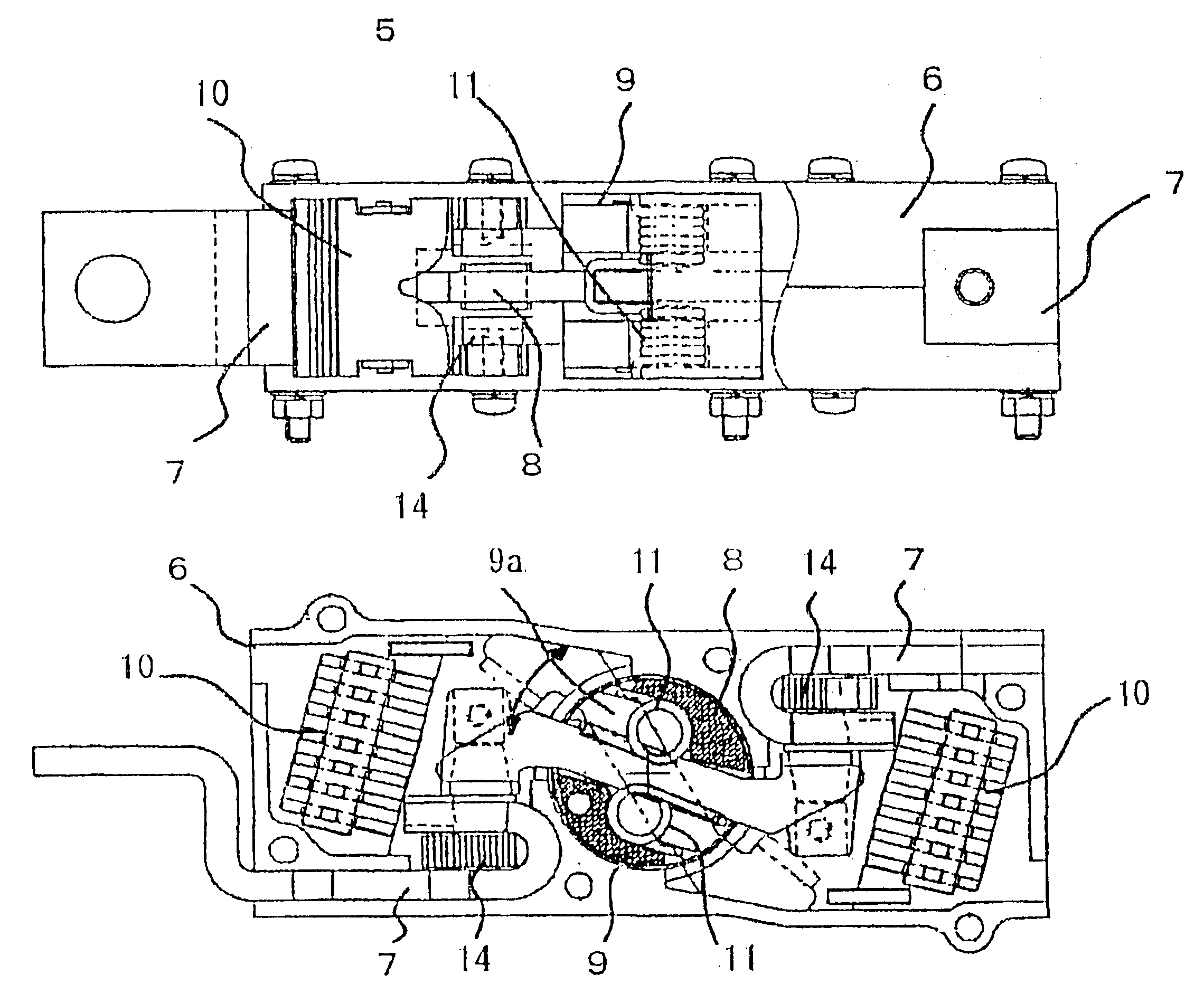
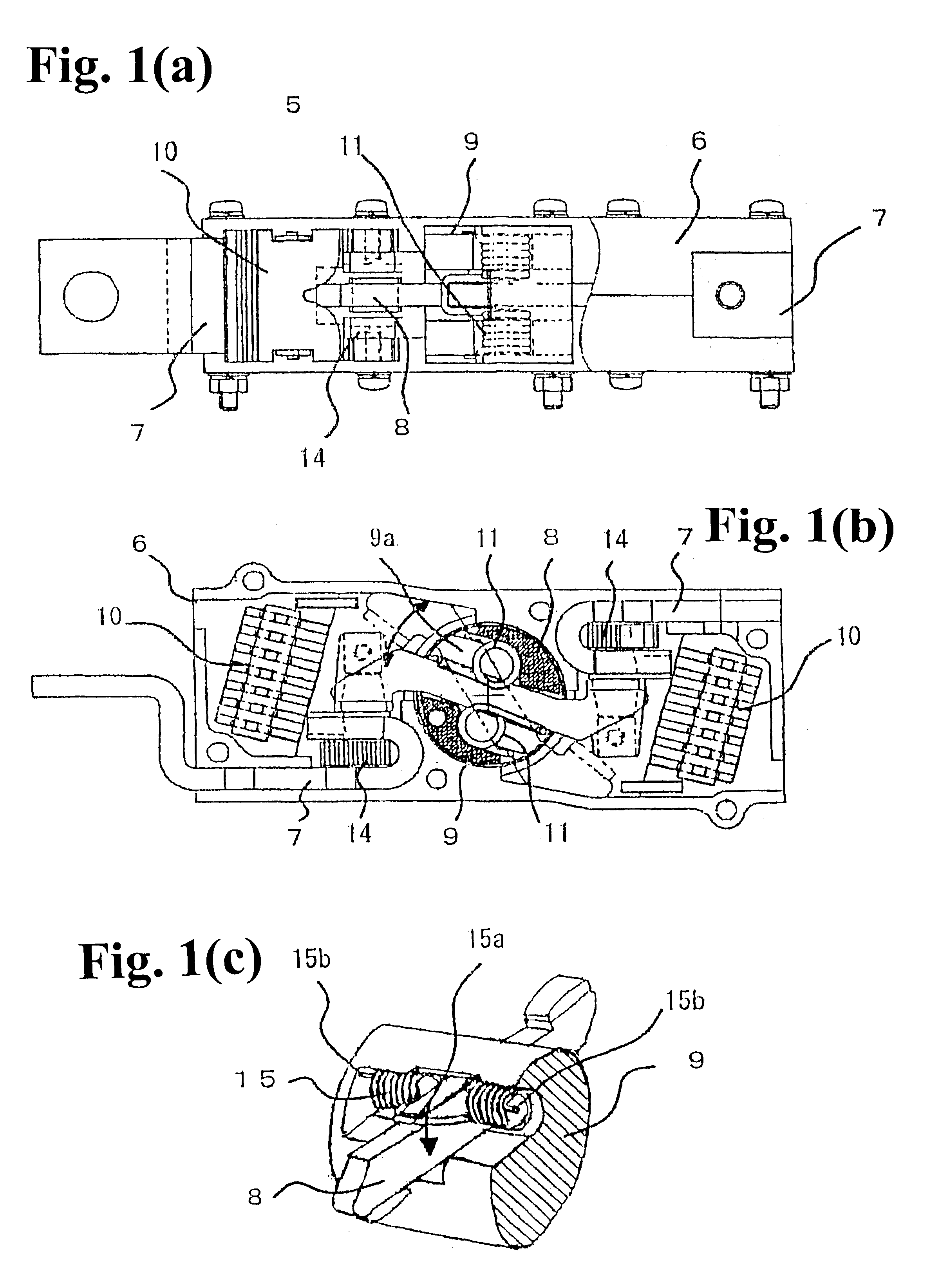
Hereunder, an embodiment of the present invention will be described with reference to the accompanied drawings. In the figures, the same parts as those in FIGS. 6(a) and 6(b) are denoted by the same reference numerals, and the description is omitted.

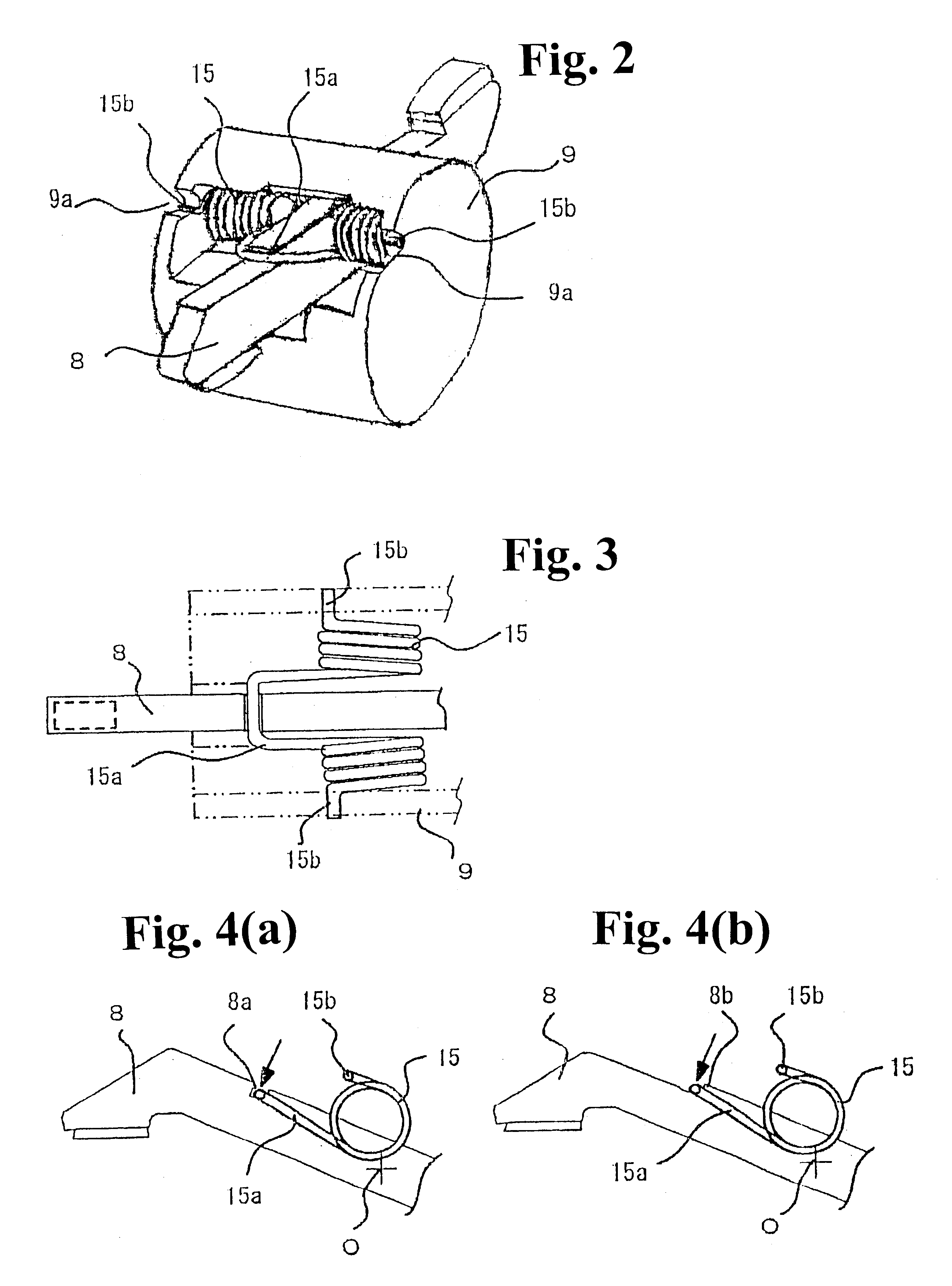
First, in FIGS. 1(a) to 1(c), a current-interrupting section 5 of a molded case circuit breaker essentially has a configuration similar to that shown in FIGS. 6(a) and 6(b), but a support structure for a movable (rotary) contact shoe 8 held in a contact shoe holder 9 is different. As shown in FIG. 1(c), as the pressure springs 11, torsion coil springs 15 with offset arms 15a are disposed above and under the movable contact shoe 8 so as to press and hold the movable contact shoe 8 in a predetermined position.

The torsion coil spring 15 has the offset arm portion 15a formed in the center of the coil. The offset arm portion 15a has a U-shape and drawn out from the coil laterally, as shown in FIG. 3. Legs 15b are provided at respective ends o...


PUM


Abstract

A current-interrupting section of a molded case circuit breaker includes fixed contact shoes and a rotary bridge-type contact shoe held in a contact shoe holder. A pair of pressure springs is assembled in the contact shoe holder to press the rotary contact shoe to the fixed contact shoes. The pressure spring is torsion coil springs and have U-shaped offset arm portion drawn out from the center of the coil. A pair of the torsion coil springs is arranged above and under the rotary contact shoe. Furthermore, legs of the torsion coil springs at ends are hooked to sidewalls of the contact shoe holder. The offset arm portions at the center of the torsion coil springs engage the rotary contact shoe at positions symmetrical with respect to the rotational center of the rotary contact shoe.

Description

BACKGROUND OF THE INVENTION AND RELATED ART STATEMENTThe present invention relates to a molded case circuit breaker, and more specifically, to an assembled structure of a current-interrupting section having fixed contact shoes and a rotary bridge-type contact shoe.First, a general configuration of a molded case circuit breaker is schematically shown in FIG. 5. In this figure, reference numeral 1 denotes a main body case of a circuit breaker, 2 is an opening and closing handle or a switching handle, 3 is a toggle type opening and closing mechanism or a switching mechanism, and 4 is an over-current tripping device (based on a bimetal method or the like). Reference numeral 5 is a current-interrupting section containing fixed contact shoes, a movable contact shoe and arc extinguishing devices of a main circuit, and is linked to the opening and closing mechanism 3. An opening and closing operation of such a circuit breaker is well known. Through an ON / OFF operation of the opening and clo...

Claims


Application Information

Patent Timeline
Patent Type & Authority Patents(United States)
IPC IPC(8): H01H73/00H01H73/04H01H1/20H01H73/02H01H73/20
CPCH01H1/205H01H73/045H01H1/2058H01H2001/223H01H73/20
Inventor UCHIDA, NAOSHIKAWAHARA, FUMIYOSHISUGIYAMA, SYUICHI
Owner FUJI ELECTRIC FA COMPONENTS & SYST CO LTD
Learn More