Structure of seat for vehicle

a technology for vehicle seats and seats, applied in the direction of roofs, safety belts, pedestrian/passenger safety arrangements, etc., can solve the problems of user or passenger inconvenience, unsatisfactory increase of seat weight, and the need for user or passenger to relocate seat belts

Inactive Publication Date: 2003-07-22
TACHI S CO LTD +1
View PDF19 Cites 36 Cited by
  • Summary
  • Abstract
  • Description
  • Claims
  • Application Information

AI Technical Summary

Benefits of technology

Accordingly, in the case of collision or sudden deceleration, a great load, applied to the seat from an occupant thereon who is restrained by the seat belt means, is imparted via the seat belt means to the seat cushion frame and quickly escaped through the lock means and striker down to the vehicle floor. Since the great load is directly exerted upon the floor or vehicle body, the seat cushion frame does not require any special reinforcement that involves a whole increased physical modification thereof, thus allowing the seat cushion frame to remain unchanged or light in weight. Also, the provision of seat belt means at the seat cushion frame insures to not only make the seat belt means readily accessible to a user or passenger even when he or she is adjusting the seat fore-and-aft position and folding the seat, but also preclude the seat belt means from being fallen down through the seat during that seat arranging work, which therefore avoids the troublesome necessity for user or passenger to find and reach out for the seat belt means fallen or missing under the seat.
It is a second purpose of the present invention to provide a seat construction which avoids an intensive exertion of the foregoing great load upon the lock mechanism and eliminates the need for reinforcing the lock mechanism itself.
For that purpose, in the seat cushion frame, there are formed a cross frame member and a longitudinal frame member extending in a direction transversely of the cross frame member, and further, firmly connected with those cross and longitudinal frame members is a vertically extending base plate to which both lock means and seat belt means are fixedly attached. Thus, the great load will be dispersed effectively into those cross and longitudinal frame members as well as the base plate, thereby avoiding an intensive load exertion on the lock mechanism and seat belt means, while simultaneously allowing direct and smooth escape of the load to the floor.

Problems solved by technology

However, the foregoing conventional seat structures, due to the seat cushion being latched to the striker provided in the slide rail, has been found defective in requiring that the slide rails themselves be greatly reinforced with its extremely increased thickness to withstand a great load input from the seat belt to the seat cushion frame when a collision or sudden deceleration occurs, which leads to an undesirable increase of the weight of seat.
But, in that case, it is necessary and quite troublesome for a user or passenger to relocate the seat belt to the seat cushion every time he or she moves the seat in the fore-and-aft direction and / or flips over the seat cushion between a normal use position and a reversed flat state.
This is because the seat belt will naturally fall under the seat cushion during that seat positioning / folding operation, thus making it annoyingly necessary for the user or passenger to reach out for the fallen seat belt, pick it up and put it on the seat cushion again.

Method used


Image

  • Structure of seat for vehicle
  • Structure of seat for vehicle
  • Structure of seat for vehicle

Examples


Embodiment Construction

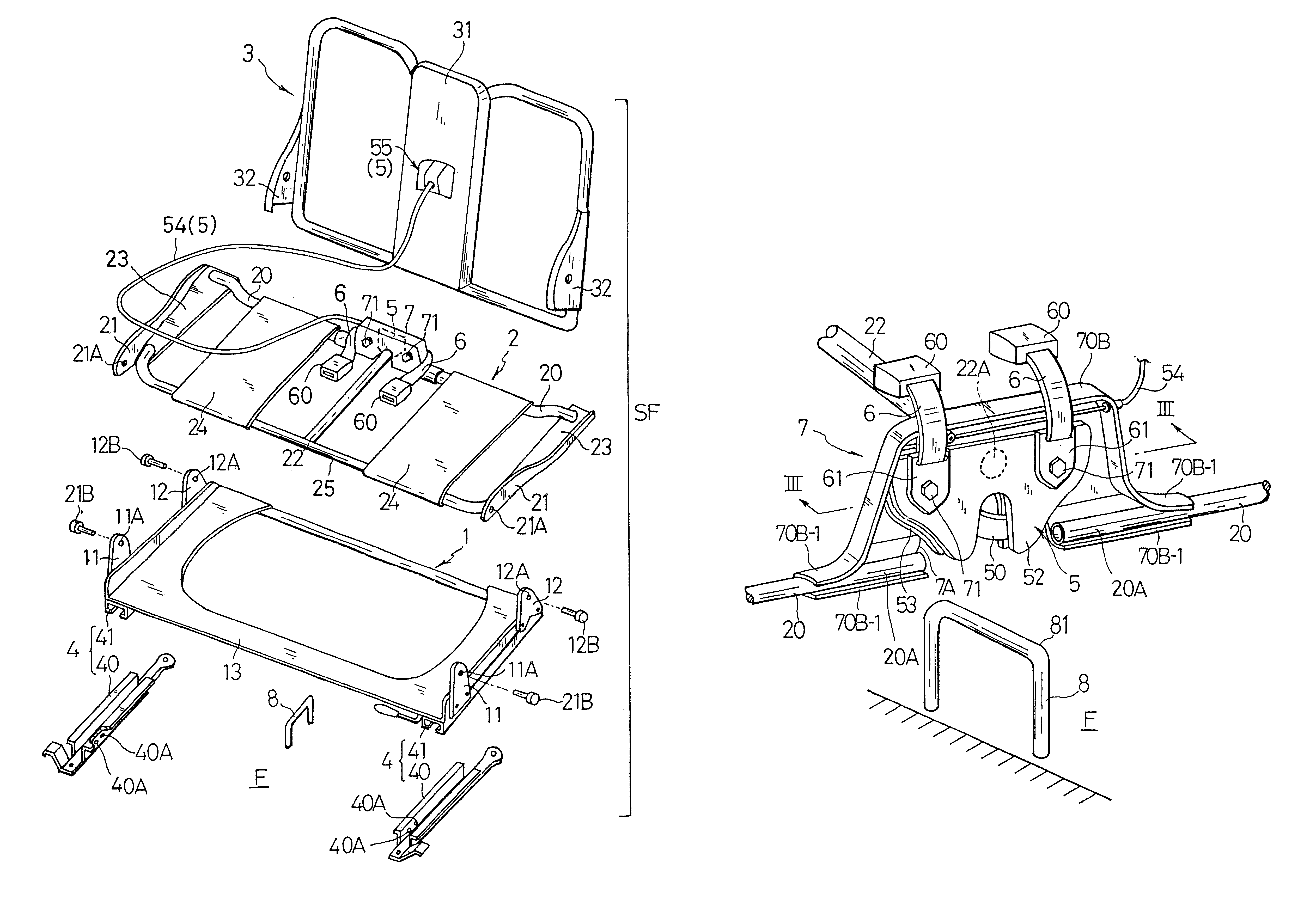
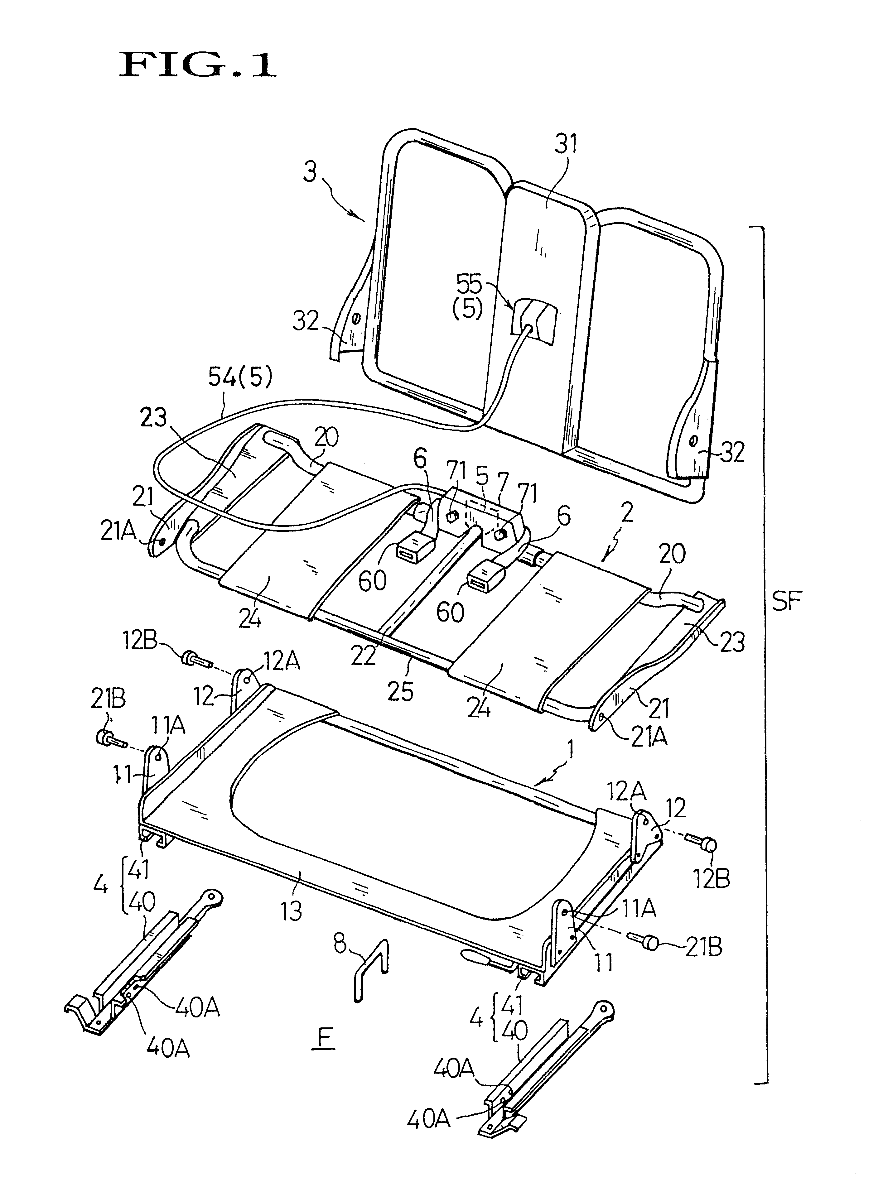
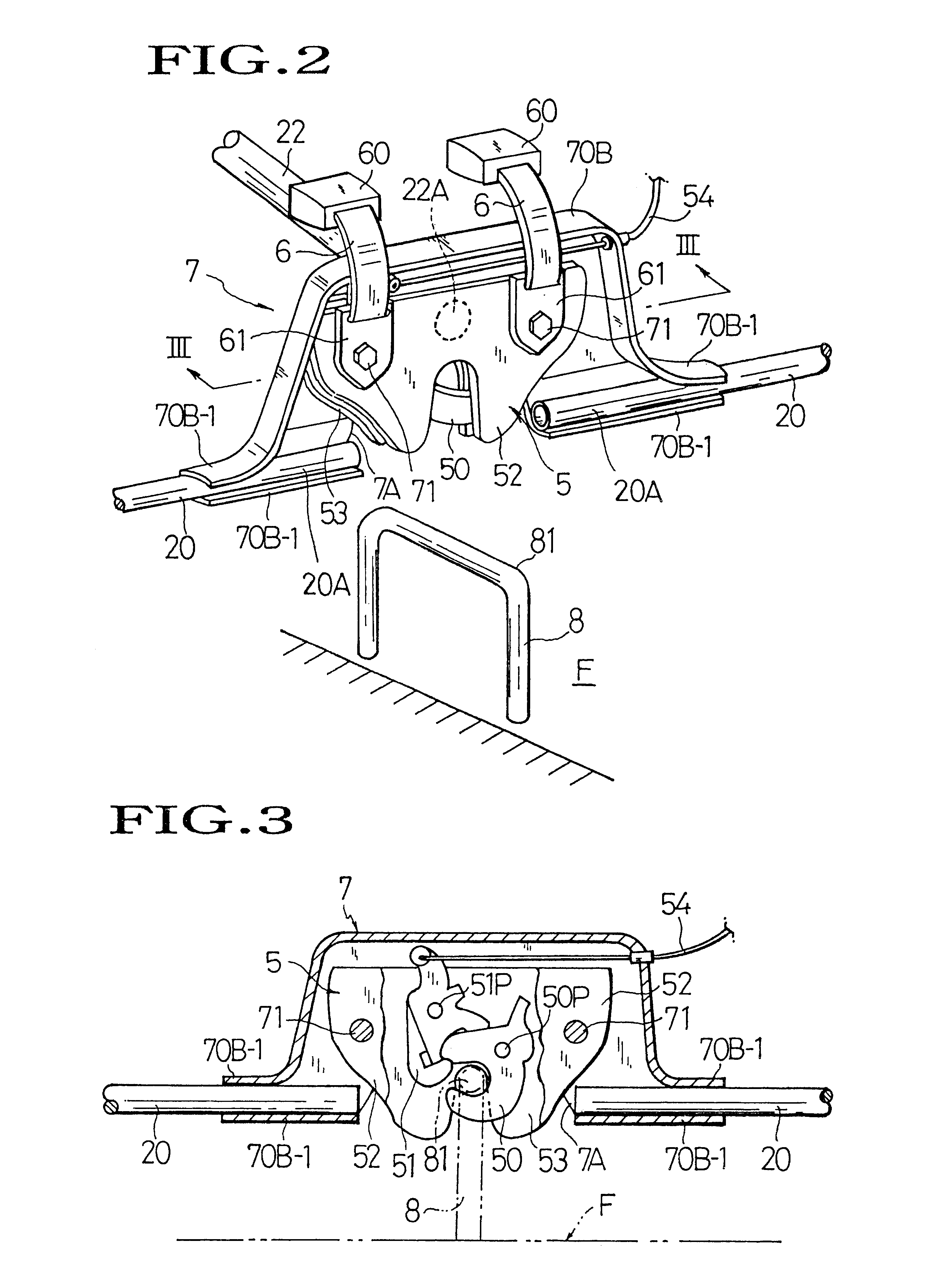
Referring to FIGS. 1 through 6, there is illustrated one exemplary mode of a vehicle seat structure in accordance with the present invention, which shows the case where a full-flat-type fold-down vehicle seat is provided, by way of example, in the present invention.

FIG. 1 schematically shows, in the perspective, an exploded framework structure of a full-flat-type fold-down vehicle seat of the present invention. The framework structure or fold-down seat frame assembly, as generally designated by (SF), basically includes a base frame (1); a seat cushion frame (2); a seat back frame (3); and a pair of slide rail devices (4) (4). Each of the slide rail devices (4) is comprised of an upper movable rail (41) having generally inverted-U-shaped cross-section and a stationary lower rail (40) having generally "T" shaped cross-section adapted to be slidably fit in such invented "U" cross-sectional upper rail (41).

As is known, the base frame (1) itself is of an ordinary rectangular configuratio...


PUM


Abstract

A structure of vehicle seat including a seat cushion frame pivoted therein, a striker, and a lock mechanism for locking and unlocking the seat cushion frame to and from the striker. The lock mechanism is disposed in the rearward area of the seat cushion frame, while the striker is fixed on the floor of vehicle, so as to allow smooth and direct escape of a great load from the seat cushion frame via the striker to the floor. This avoids the necessity of any reinforcement leading to weight increase of the seat. Also, a seat belt is provided in the seat cushion frame together with the lock mechanism in an integral manner.

Description

BACKGROUND OF INVENTION1. Field of the InventionThe present invention generally relates to a vehicle seat structure. In particular, the invention is directed to a structure of vehicle seat which is effective in withstanding a great load and also applicable to a fold-down vehicle seat which allows its seat back and seat cushion to be folded or flipped over into a full-flat seat state.2. Description of Prior ArtAmong various sorts of vehicle seats, there is known a folding or fold-down seat structure wherein a seat back frame and / or a seat cushion frame are / is foldable into a compact folded state to widen a space in a vehicle. Also, known is a full-flat type of fold-down seat structure wherein a seat back frame and a seat cushion frame are both so articulated on a base frame as to be foldable into a full-flat state where the rear surfaces of the seat back and cushion frames lie generally flush with each other to provide an enlarged floor or cargo load space in the rearward cabin regio...

Claims


Application Information

Patent Timeline
Patent Type & Authority Patents(United States)
IPC IPC(8): B60N2/30B60N2/36B60R22/26B60N2/32B60R22/18B60R22/02B60N2/42
CPCB60N2/3013B60N2/305B60N2/366B60R22/26B60R2022/021B60R2022/1806
Inventor KONISHI, TATSUYATERASAKI, TSUTOMUSEKITA, ISAO
Owner TACHI S CO LTD
Why Eureka
Try Eureka